
Display and sub-pixel driving method therein

a technology of display and sub-pixels, applied in the field of display, can solve the problems of abnormal pixels of the image displayed on the -led display that cannot be fixed, and the components of led components have worse contact with the glass substrate transistors,

Active Publication Date: 2015-11-26
AU OPTRONICS CORP
View PDF4 Cites 15 Cited by
  • Summary
  • Abstract
  • Description
  • Claims
  • Application Information

AI Technical Summary

Benefits of technology

The patent text describes the advantages of μ-LED display technology, but also highlights the current limitations of bonding LED components onto a glass substrate. This can result in non-uniform pixel brightness and image quality issues, such as dark spots or abnormal pixels. The technical effect of this patent is to provide a solution to improve the bonding of LED components onto a glass substrate to reduce these issues and improve the overall quality of μ-LED display technology.

Problems solved by technology

However, since technique for bonding LED components on the glass substrate is immature, LED components have worse contact with transistors of the glass substrate.
Since illumination efficiency of the LED component is reduced, luminance of pixels of a display image is decreased, resulting in that luminance of displayed image becomes non-uniform.
When aforementioned conditions are occurred, abnormal pixels of the image displayed on the μ-LED display fail to be fixed.

Method used


Image

  • Display and sub-pixel driving method therein
  • Display and sub-pixel driving method therein
  • Display and sub-pixel driving method therein

Examples


Embodiment Construction

[0017]Reference will now be made in detail to the present embodiments of the disclosure, examples of which are illustrated in the accompanying drawings. Wherever possible, the same reference numbers are used in the drawings and the description to refer to the same or like parts.

[0018]It will be understood that, although the terms first, second, third etc. may be used herein to describe various elements, components, regions, layers and / or sections, these elements, components, regions, layers and / or sections should not be limited by these terms. These terms are only used to distinguish one element, component, region, layer or section from another element, component, region, layer or section. Thus, a first element, component, region, layer or section discussed below could be termed a second element, component, region, layer or section without departing from the teachings of the present invention.

[0019]It will be understood that when an element is referred to as being “connected” or “co...


PUM


Abstract

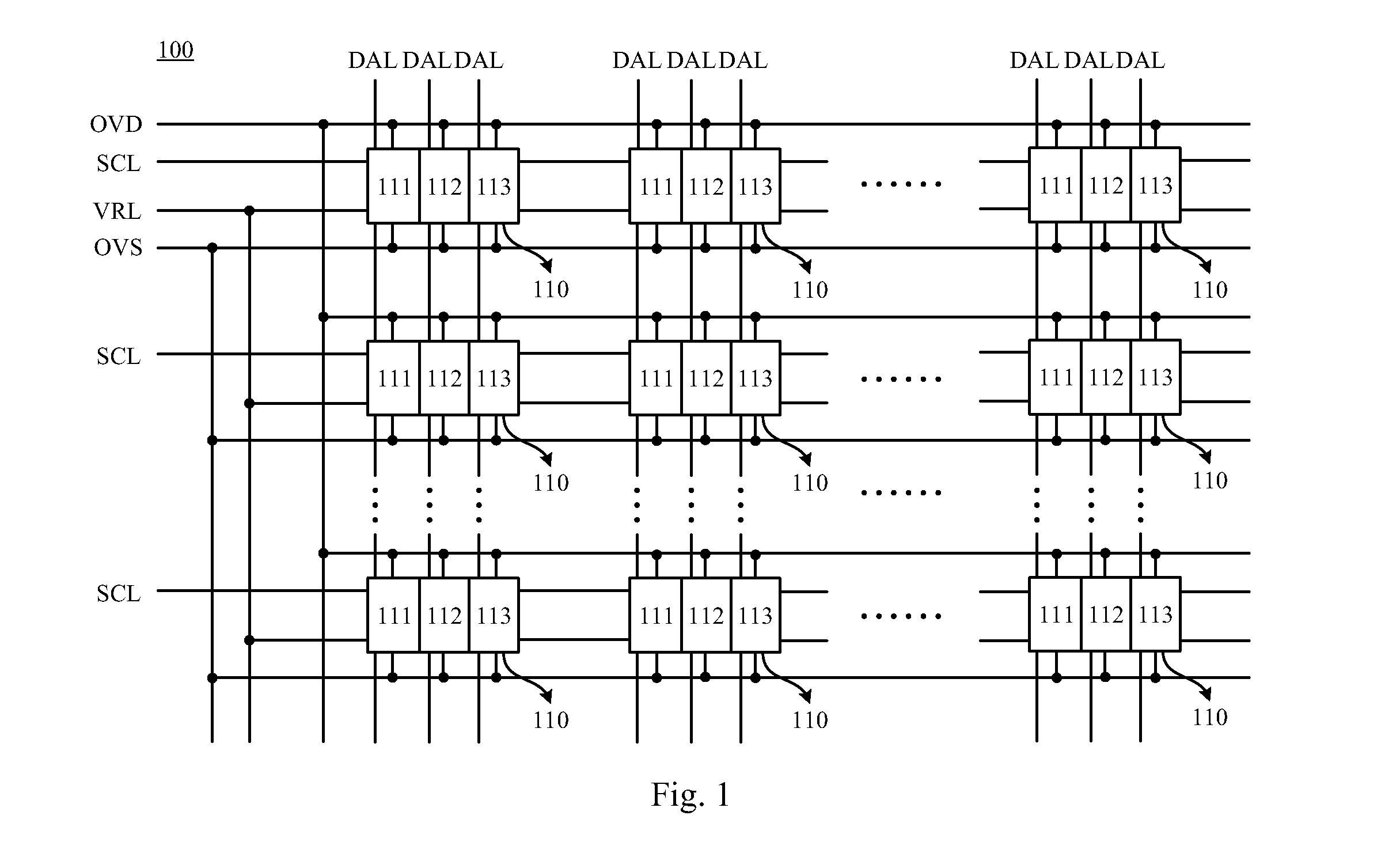
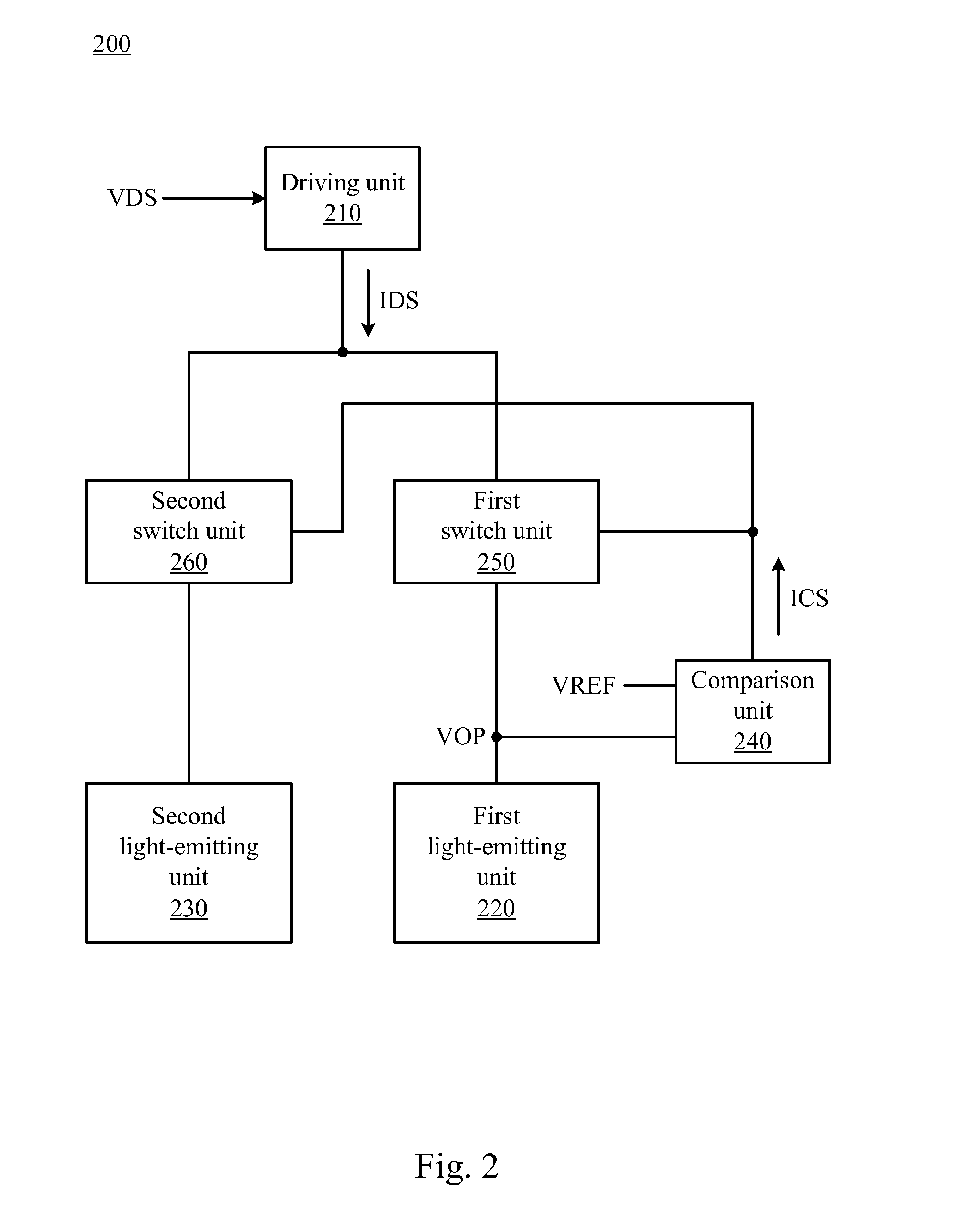
A display and a sub-pixel driving method therein are provided. The display includes a data line and a sub-pixel. The data line is configured to provide a data voltage signal. The sub-pixel includes a driving unit, a first light-emitting unit and a second light-emitting unit. The driving unit is configured to generate a driving current according to the data voltage signal. The first light-emitting unit is configured to emit light by the driving current and generate an operating voltage according to the driving current. The second light-emitting unit is selectively substituted for the first light-emitting unit to emit light according to a variation of the operating voltage.

Description

RELATED APPLICATIONS[0001]This application claims priority to Taiwan Application Serial Number 103118124 filed May 23, 2014 which is herein incorporated by reference.BACKGROUND[0002]1. Technical Field[0003]The present disclosure relates to a display. More particularly, the present disclosure relates to a light-emitting diode display.[0004]2. Description of Related Art[0005]Since micrometer scale-light-emitting diode (μ-LED) display uses μ-LED components as pixels for display, it is unnecessary to additionally set a backlight module in the μ-LED display. Therefore, the μ-LED display has advantages such as simple architecture, thin thickness, high contrast, wide viewing angle, fast response, etc. However, since technique for bonding LED components on the glass substrate is immature, LED components have worse contact with transistors of the glass substrate. When the display is turned on in a long period, inner resistance of a LED component is increased. Therefore, when the LED componen...

Claims


Application Information

Patent Timeline
IPC IPC(8): G09G3/32G09G5/10G09G3/20H05B37/02G09G3/3208
CPCG09G3/3233H05B37/02G09G2310/0264G09G3/2074G09G5/10G09G2300/0452G09G2300/0804G09G2320/043
Inventor LIU, YI-CHENG
Owner AU OPTRONICS CORP
Learn More