
Image forming apparatus and image forming method

a technology of image forming apparatus and forming method, which is applied in the direction of electrographic process apparatus, instruments, optics, etc., can solve the problems of deteriorating picture quality and the possibility of deteriorating density unevenness, and achieve the effect of suppressing density unevenness of visible imag

Active Publication Date: 2015-11-26
KYOCERA DOCUMENT SOLUTIONS INC
View PDF4 Cites 7 Cited by
  • Summary
  • Abstract
  • Description
  • Claims
  • Application Information

AI Technical Summary

Benefits of technology

This patent describes an image forming apparatus that can control the distance between the photosensitive drum and the developing roller, which affects the quality of the image. The apparatus can record this distance during assembly and use it to control the intensity of the light beam that irradiates the image surface, resulting in better control of image quality.

Problems solved by technology

The variation of the toner adhering amount appears as the density unevenness of the visible image, which deteriorates the picture quality.
In addition, the rotation speed of the photosensitive drum is not always identical with the rotation speed of the developing roller, and the circumference of the photosensitive drum is not constant multiples of the circumference of the developing roller.
Therefore, there is a possibility to deteriorate the density unevenness moreover by applying the above-mentioned art to the image forming apparatus.

Method used


Image

  • Image forming apparatus and image forming method
  • Image forming apparatus and image forming method
  • Image forming apparatus and image forming method

Examples


Embodiment Construction

[0029]The embodiments of the present disclosure will be more specifically explained hereinafter with reference to the attached drawings. The present disclosure is materialized by a digital multifunction peripheral.

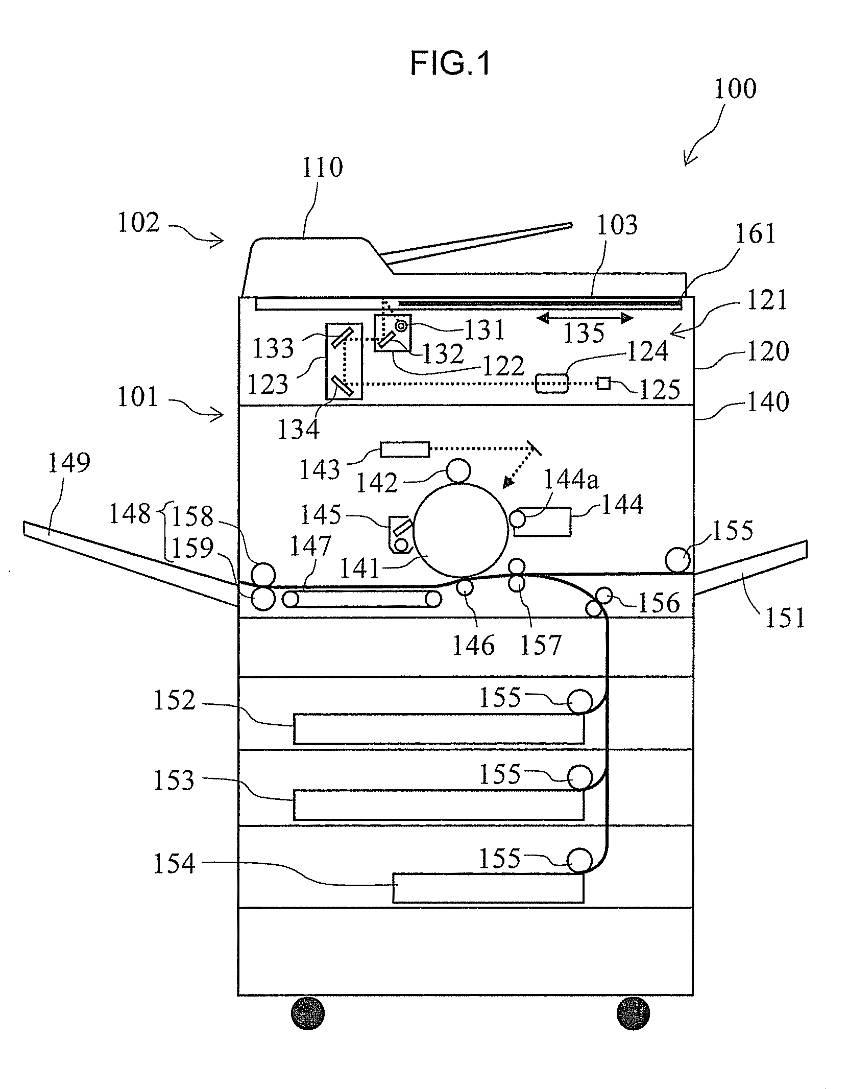
[0030]FIG. 1 is a schematic view showing the whole structure of the digital multifunction peripheral in this embodiment. As shown in FIG. 1, the multifunction peripheral 100 includes a base machine 101 having an image reading unit 120 and an image forming unit 140, and a platen cover 102 placed over the base machine 101. An original plate 103 made of a transparent plate such as a contact glass is arranged on a top surface of the base machine 101. The original plate 103 is opened and closed by the platen cover 102. The platen cover 102 is provided with a document feeder 110. The multifunction peripheral 100 is provided on its front side with an operation panel 161 whereby user can give the multifunction peripheral 100 a copy start instruction and other instructions, and als...


PUM


Abstract

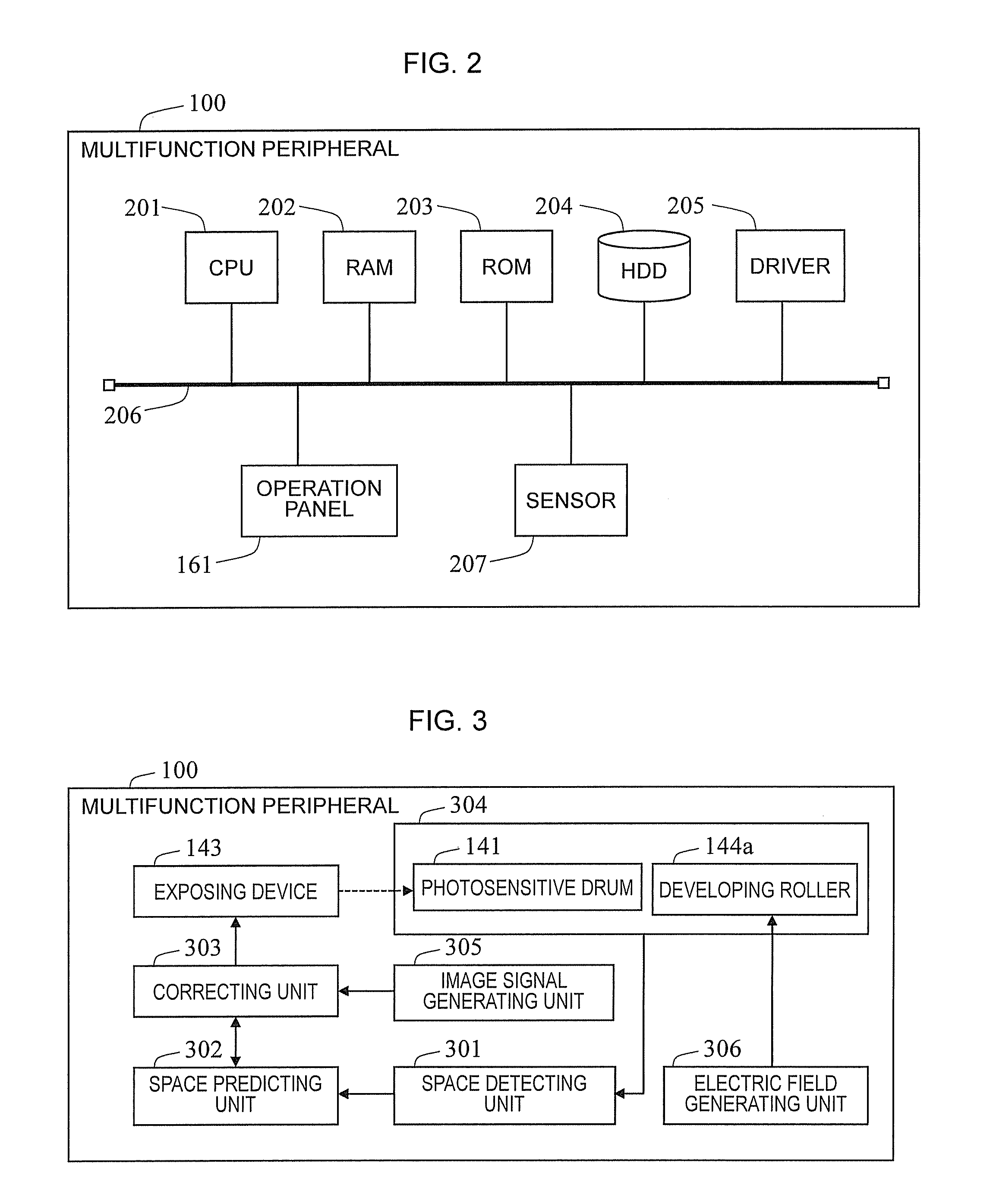
In the image forming apparatus, the space detecting unit detects the space between the image carrying surface and the developer carrying surface. The correcting unit corrects the intensity of the development field for developing the electrostatic latent image on the image carrying surface based on the acquired correspondence relation and the space detected by the space detecting unit, for example. In this case, the correspondence relation is a relation between the image density of the visible image transferred from the image carrying surface to the transferred medium and the development filed for suppressing the density unevenness of the visible image.

Description

INCORPORATION BY REFERENCE[0001]This application claims the benefit of Japanese Patent Application No. 2013-112880, filed on May 29, 2013 and Japanese Patent application No. 2013-112881, filed on May 29, 2013, all of which are hereby incorporated by reference in their entireties.BACKGROUND OF THE INVENTION[0002]The present disclosure relates to an image forming apparatus and an image forming method for forming an electrophotographic image.[0003]The electrophotographic image forming apparatus such as the printer or the copying machine forms an image by performing a series of steps including the charging step, the exposure step, the developing step, the transferring step, and the fixing step. The charging step is for uniformly electrifying a photosensitive drum. The exposing is for exposing an electrified photosensitive drum and forming an electrostatic latent image thereon. The developing is for adhering toners to the electrostatic latent image and forms a visible image. The transfer...

Claims


Application Information

Patent Timeline
Patent Type & Authority Applications(United States)
IPC IPC(8): G03G15/043G03G15/06
CPCG03G15/043G03G15/5041G03G15/065G03G15/0813
Inventor NAKAGAWA, TATSUYA
Owner KYOCERA DOCUMENT SOLUTIONS INC
Learn More