
Luminaire ceiling mounting mechanism

a technology of mounting mechanism and luminaire, which is applied in the direction of fixed installation, lighting and heating apparatus, lighting support devices, etc., can solve the problems of installation and maintenance challenges that are further complicated, the installation and maintenance is complicated, and the installation is difficult, so as to improve the ease of installation of luminaires

Active Publication Date: 2015-11-19
GE HUNGARY +1
View PDF13 Cites 14 Cited by
  • Summary
  • Abstract
  • Description
  • Claims
  • Application Information

AI Technical Summary

Benefits of technology

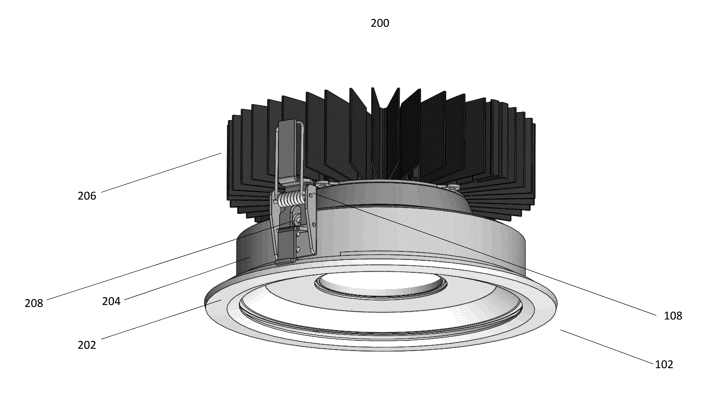
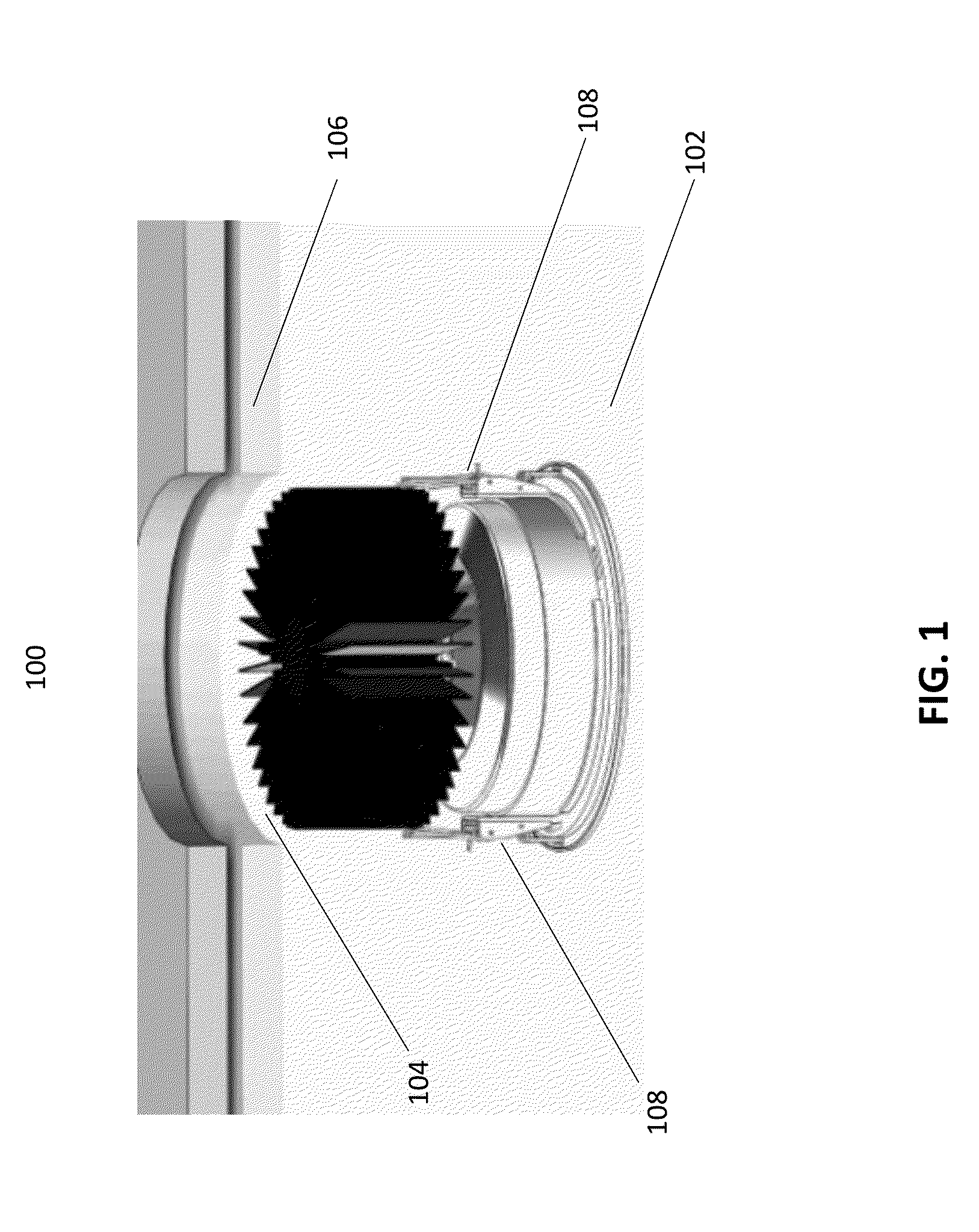
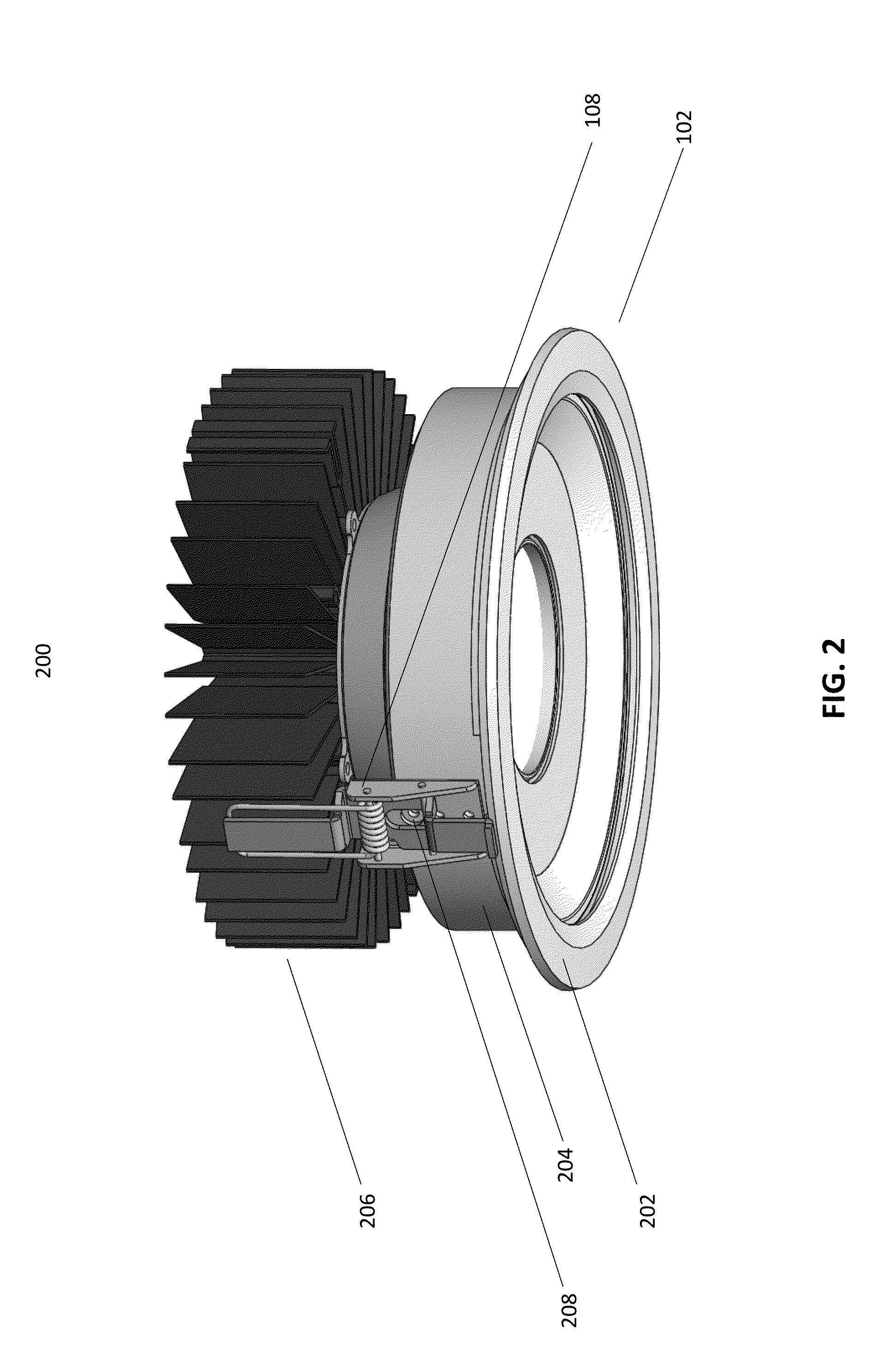
The present invention is about improving the installation of luminaires and other recessed fixtures into a ceiling, wall, or other flat member. The invention includes a mounting system that allows for easy and safe installation without the need for multiple directions of movement or the use of complex shapes or technologies. The mounting system includes a base and engagement mechanism that facilitates movement of the fixture within a recess in a flat member in only a single direction, responsive to an applied force. The technical effects of the invention are enhanced freedom of movement for the installer, simplified installation process, increased safety, and reduced risk of injury during installation.

Problems solved by technology

High-ceiling luminaire applications, however, are generally associated with inherent maintenance inefficiencies.
For example, in addition to costs associated with lamp replacement, lifts and scaffolding are usually required to safely perform installation and maintenance for high-ceiling luminaires.
These installation and maintenance challenges are further complicated because many of these luminaires are recessed and simply difficult to install or remove.
Such designs can present a risk of injury to the installer and can actually make the installation process more complicated.

Method used


Image

  • Luminaire ceiling mounting mechanism
  • Luminaire ceiling mounting mechanism
  • Luminaire ceiling mounting mechanism

Examples


Embodiment Construction

[0005]Given the aforementioned deficiencies, a need exists for mounting systems and methods to improve the ease of installation of luminaires, and other recessed fixtures, into a ceiling, wall, or into some other substantially flat member.

[0006]In certain circumstances, an embodiment of the present invention includes a device including a base configured for attachment to a lighting fixture. The device also includes an engagement mechanism having first and second portions configured for mounting the lighting fixture within a recess of a substantially flat member having first and second ends. The engagement mechanism facilitates movement of the lighting fixture within the recess from the first end towards the second end, the movement (i) being responsive to an applied force and (ii) occurring in only a single direction. The first portion engages a first surface of the member and the second portion engages a second surface of the member when the lighting fixture reaches the second end....


PUM

PropertyMeasurementUnit
applied forceaaaaaaaaaa
forceaaaaaaaaaa
tensionaaaaaaaaaa

Abstract

Provided is a device including a base configured for attachment to a lighting fixture. The device also includes an engagement mechanism having first and second portions configured for mounting the lighting fixture within a recess of a substantially flat member having first and second ends. The engagement mechanism facilitates movement of the lighting fixture within the recess from the first end towards the second end, the movement (i) being responsive to an applied force and (ii) occurring in only a single direction. The first portion engages a first surface of the member and the second portion engages a second surface of the member when the lighting fixture reaches the second end.

Description

I. FIELD OF THE INVENTION[0001]The present invention generally relates to installation of lighting fixtures, or luminaires. More particularly, the present invention relates to mechanisms for mounting luminaire systems in locations, such as ceilings, in a safe, efficient, and cost-effective manner.II. BACKGROUND OF THE INVENTION[0002]Luminaires are increasingly relied upon for white light production in downlight high-ceiling applications. These applications provide a lighting for offices, retail space settings, and other commercial applications. Additionally, more recently developed downlight luminaires also include advanced lighting technology that is inherently more sustainable, while providing significant energy savings than predecessor, or legacy systems.[0003]High-ceiling luminaire applications, however, are generally associated with inherent maintenance inefficiencies. For example, in addition to costs associated with lamp replacement, lifts and scaffolding are usually required...

Claims


Application Information

Patent Timeline
Patent Type & Authority Applications(United States)
IPC IPC(8): F21V21/03F21V21/04
CPCF21V21/03Y10T29/49948F21V21/04F21S8/04F21V21/02F21S8/026F21V21/046
Inventor ABAI, ROBERTSIMONYI, BULCSUFENDRIK, ARMIN GYULAROZSAS, ISTVAN
Owner GE HUNGARY
Learn More