Control system for transmission

Active Publication Date: 2011-03-10
HONDA MOTOR CO LTD
View PDF7 Cites 12 Cited by
  • Summary
  • Abstract
  • Description
  • Claims
  • Application Information

AI Technical Summary

Benefits of technology

[0007]With the configuration according to the first feature of the present invention, a hydraulic circuit for a twin-clutch transmission includes: the first shift valve operated by the first shift solenoid, the first shift valve being configured to supply the hydraulic pressure, which is outputted by the first hydraulic pressure regulating device, to the first clutch or one of the first hydraulic actuators; the second shift valve operated by the second shift solenoid, the second shift valve being configured to supply the hydraulic pressure, which is outputted by the second hydraulic pressure regulating device, to the second clutch or one of the second hydraulic actuators; the third shift valve operated by the third shift solenoid, the third shift valve being configured to supply the hydraulic pressures, which are outputted by the respective first and second shift valves, selectively to one of the first and second hydraulic actuators; and the fourth shift valve placed between the third shift valve and the second hydraulic actuators, the fourth shift valve being operated by the first shift solenoid. For this reason, when the third shift valve operated by the third shift solenoid goes out of order and the shift change accordingly becomes incapable of being carried out, the hydraulic pressure, which is outputted from the broken third shift valve, is controlled by the fourth shift valve which is operated by the first shift solenoid. Thereby, the hydraulic pressure which is outputted by the second hydraulic pressure regulating device can be supplied to one of the second hydraulic actuators, and this enables one of the second predetermined transmission gear stages to be pre-shifted by use of the second power transmission path. In the case where the first shift valve is used as a fail-safe as described above, the hydraulic pressure outputted by the first hydraulic pressure regulating device can be supplied to none of the first hydraulic actuators and the first clutch, and none of the first predetermined transmission gear stages accordingly can be pre-shifted by use of the first power transmission path. Consequently, the vehicle is not capable of running with any one of the first predetermined transmission gear stages. However, the configuration according to the first feature thereof enables the one of the second predetermined transmission gear stages to be set up, and accordingly makes it possible for the vehicle to make a minimum necessary run. Furthermore, the configuration according to the first feature thereof drives the fourth shift valve by use of the existing first shift solenoid for driving the existing first shift valve. For this reason, it is possible to keep the increase in the number of parts and costs to a minimum.
[0011]With the configuration according to the third feature of the present invention, the third shift valves are made up of two shift valves placed in series, and accordingly it is possible to increase the number of transmission gear stages while keeping the number of third shift valves to a minimum.
[0013]With the configuration according to the fourth feature of the present invention, the two shift valves, which are placed in series, are operated by the respective third shift solenoids, and accordingly it is possible to increase the number of transmission gear stages by controlling the positions of each of the two shift valves separately.
[0015]With the configuration according to the fifth feature of the present invention, the first and fourth shift valves are made as the respective separated bodies, and thus it is possible to make the total length of the first and fourth shift valves shorter than the total length of the first and fourth shift valves which are formed integrally, thereby enhancing ease of installation of the first shift and fourth shift valves.

Problems solved by technology

Consequently, the vehicle is not capable of running with any one of the first predetermined transmission gear stages.

Method used


Image

  • Control system for transmission
  • Control system for transmission
  • Control system for transmission

Examples


first embodiment

[0036]Hereinafter, descriptions will be provided for the present invention on the basis of FIGS. 1 to 10.

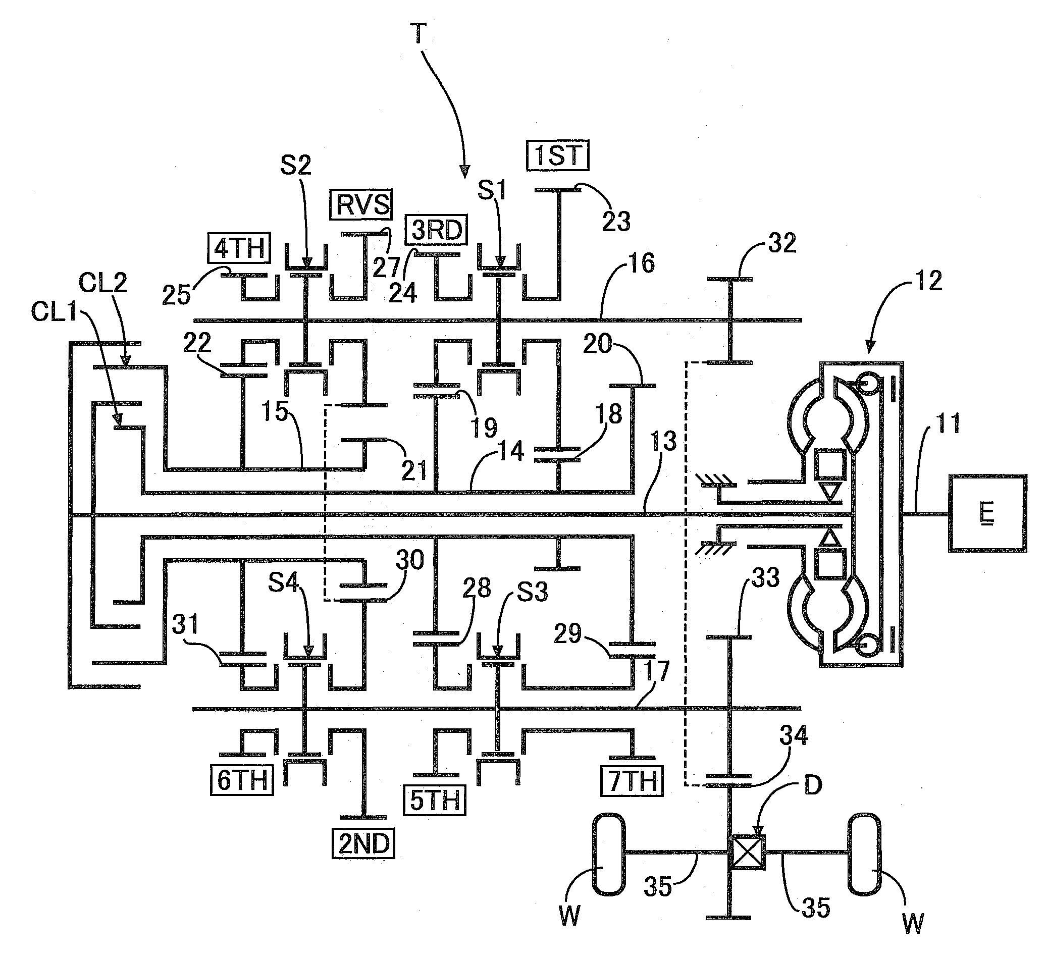
[0037]FIG. 1 shows a skeleton of a twin-clutch automatic transmission for providing seven forward speeds and one reverse speed. An automatic transmission T includes a main input shaft 13 into which a driving force of a crank shaft 11 of an engine E is inputted via a torque converter 12. A first auxiliary input shaft 14 and a second auxiliary input shaft 15 are fitted to an outer periphery of the main input shaft 13 coaxially and rotatably relative to the main input shaft 13. The main input shaft 13 and the first auxiliary input shaft 14, which is inner in a radial direction, are capable of being connected together through a wet multi-plate first clutch CL1. The main input shaft 13 and the second auxiliary input shaft 15, which is outer in the radial direction, are capable of being connected together through a wet multi-plate second clutch CL2. In addition, a first output shaft 16...

second embodiment

[0090]Next, descriptions will be provided for a second embodiment on the basis of FIGS. 11 to 16.

[0091]In the first embodiment, the first shift valve VA1 and the fourth shift valve VA4 are formed integrally. In addition, the first shift valve VA1 and the fourth valve VA4 are driven together by the first shift solenoid SH1. In the second embodiment, as shown in FIG. 11, the fourth shift valve VA4 is formed as a body independent of the first shift valve VA1. However, the fourth shift valve VA4 operates integrally with the first shift valve VA1 because the fourth shift valve VA4 is connected to the first shift solenoid SH1 via a hydraulic path.

[0092]In the first embodiment, what is obtained by integrating the first shift valve VA1 and the fourth shift valve VA4 together is too long, and this excessive length may be an obstacle to the housing of the first shift valve VA1 and the fourth shift valve VA4 in a valve block. In the second embodiment, the separation of the first shift valve VA...


PUM


Abstract

In a twin-clutch transmission, when a third shift valve (for example) goes out of order and the shift change accordingly becomes incapable of being carried out, the hydraulic pressure outputted from the third shift valve is controlled by a fourth shift valve operated by a first shift solenoid for a first shift valve. Accordingly, the hydraulic pressure outputted by a second linear solenoid is supplied to one of second hydraulic actuators, thereby enabling one of second predetermined transmission gear stages to be pre-shifted by use of a second power transmission path. When the first shift valve is used as a fail-safe, it is possible for the vehicle to make a minimum necessary run by setting up one of the second predetermined transmission gear stages. Furthermore, the fourth shift valve is driven by use of the existing first shift solenoid, thus minimizing the number of parts and cost.

Description

BACKGROUND OF THE INVENTION[0001]The present invention relates to a control system for what is termed as a twin-clutch transmission. The twin-clutch transmission is configured to set up multiple transmission gear stages by use of a first power transmission path for transmitting a driving force of an engine to driving wheels via a first clutch, and to set up the other multiple transmission gear stages by use of a second power transmission path for transmitting the driving force of the engine to the driving wheels via a second clutch.[0002]Such a twin-clutch transmission is designed to accomplish shift-up and shift-down by repeatedly sequentially carrying out: the pre-shifting of an even-numbered speed transmission gear stage while an odd-numbered speed transmission gear stage is being set up with engagement of the first clutch; the setting up of the even-numbered speed transmission gear stage once the second clutch is engaged in exchange for disengagement of the first clutch; the pre...

Claims


Application Information

Patent Timeline
IPC IPC(8): F16H61/30
CPCF16H3/006F16H61/12F16H61/2807F16H61/688F16H2003/0931F16H2061/1224Y10T74/19307F16H2061/126Y10T74/19167Y10T74/20024Y10T74/19251Y10T74/1926F16H2200/0056
Inventor SATO, TAKAO
Owner HONDA MOTOR CO LTD
Why Eureka
Try Eureka