
Wall furniture mounting rail

a technology for wall furniture and mounting rails, which is applied to furniture parts, machine supports, and suspension devices, etc., can solve the problems of inconvenient installation of wall furniture, poor mounting effect, and inability to meet the needs of wall furniture, etc., and achieves the effect of convenient and fast installation of wall furnitur

Inactive Publication Date: 2008-07-24
GRASS AMERICA
View PDF21 Cites 12 Cited by
  • Summary
  • Abstract
  • Description
  • Claims
  • Application Information

AI Technical Summary

Benefits of technology

[0010]The present invention is a mounting rail used in hanging wall furniture. The present invention improves the ease of installation of the mounting rail by eliminating the redundant steps of finding wall-studs. The present invention is secured to a wall so that a complementary rail on a piece of furniture to be hung can engage with it. The rail on the furniture engages with the mounting rail of the present invention and securely holds the wall furniture in place.
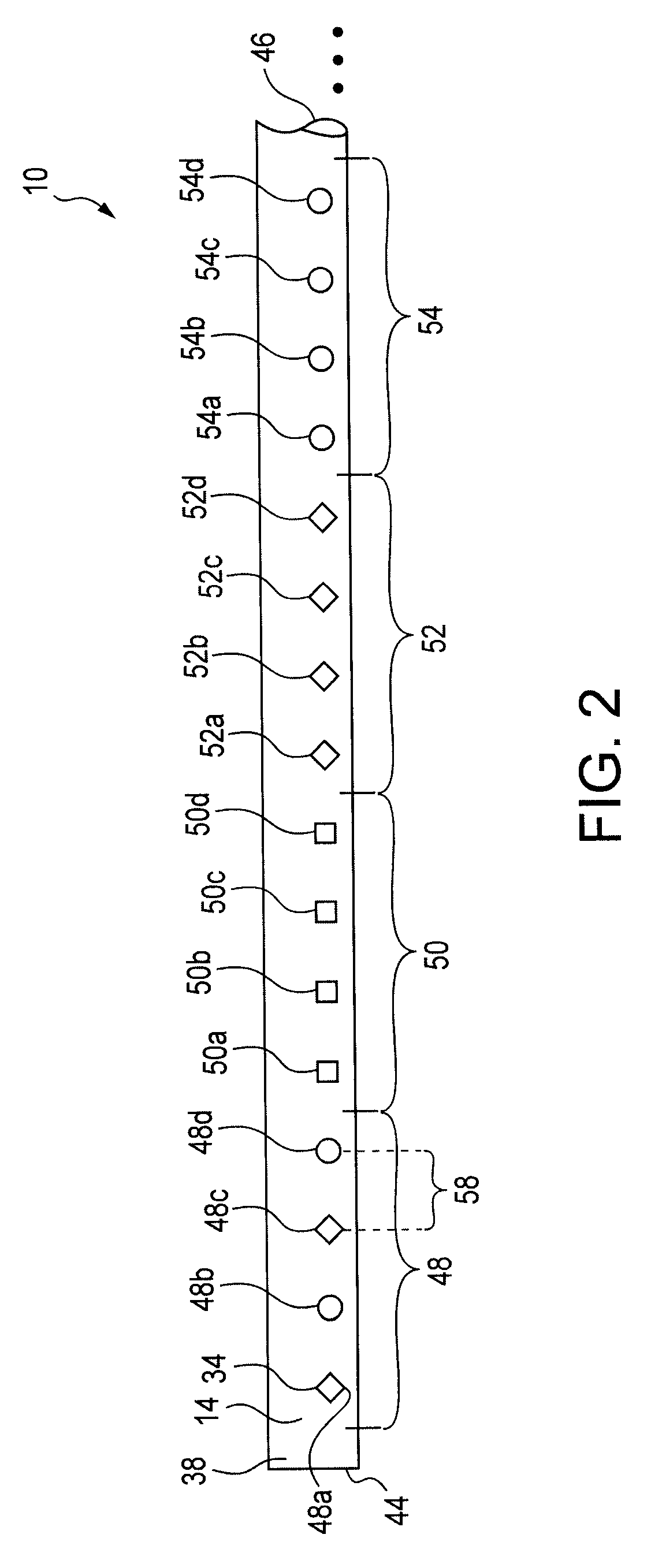
[0011]The present invention is an improvement over the prior art in the way the mounting rail attaches to the wall. The mounting rail has a series of holes or apertures, which allow the installer to locate framing studs behind the wall easily and without using a measuring tape or other measuring tool. In the preferred version of the invention, the series of apertures are arranged in a visually perceivable pattern spaced at 16-inch intervals to match the standard of 16-inch on-center spacing of wall studs that is commonly used in North America.
[0013]The present invention makes it easier and faster to install wall furniture by reducing the need to measure 16 inches (or some multiple of 16 inches) from the first found stud to a subsequent stud in order to level the mounting rail. In one embodiment, each unique pattern includes 16 individually distinguishable apertures. Along a single section of rail, the pattern may repeat several times. Once a first aperture is chosen, the second iteration of that aperture will occur 16 inches in either direction from the first aperture. The third iteration will occur another 16 inches away from the second aperture and 32 inches from the first aperture. In another embodiment, the unique pattern of 16 apertures may be comprised of a subset of patterned apertures. For example, a single 16-aperture section may be comprised of four sets of four uniquely identifiable apertures.

Problems solved by technology

Misalignment is immediately perceptible and very unsightly.
For example, kitchen cabinets tend to be loaded to their full capacity with very heavy, very expensive, and fragile items such as china, glassware, and the like.
In light of these requirements (as well as the permanent nature of most wall furniture installations), a great deal of time, care, and effort is expended by installers to ensure that the furniture is both level and securely fixed to the wall studs.
However, as in most fields, time is money in the construction trades.
Both residential and commercial buildings put heavy stress on shelving, cabinetry, and the like.
Even cabinets constructed with quality materials lose their appeal if they are mounted poorly on the wall.
Cabinets that are not mounted level and flush detract immensely from the overall appearance of the kitchen or other room.
In this environment, there are added risks not encountered in a residential kitchen.
Installation problems are due to the furniture itself (e.g., a large, fully-assembled wooden cabinet, with a door having glass inserts, is very heavy, cumbersome, and easily breakable).
Some installation problems are due to widely standardized (and usually legally-mandated) construction practices.
As a result, there is usually only limited alignment (width-wise) of the wall furniture with the underlying studs in the wall.
As a result, it is difficult (and sometimes impossible), to secure an individual unit of wall furniture directly to a stud to obtain the required secure mounting.
This creates a potentially dangerous situation when the installed furniture is loaded to capacity with heavy items.
As noted earlier, installing and leveling wall furniture (especially larger cabinets and long shelving units) is difficult due to the sheer size and weight of the individual furniture units.
While there have been improvements in the design and functionality of cabinet rails, those improvements have been limited to the interaction between the rail that is attached to the wall and the mating rail that is attached to the back of the cabinets.
The prior art mounting rails do not provide a mechanism that allows the cabinets to be installed in a level fashion quickly and with only one person.

Method used


Image

  • Wall furniture mounting rail
  • Wall furniture mounting rail
  • Wall furniture mounting rail

Examples


Embodiment Construction

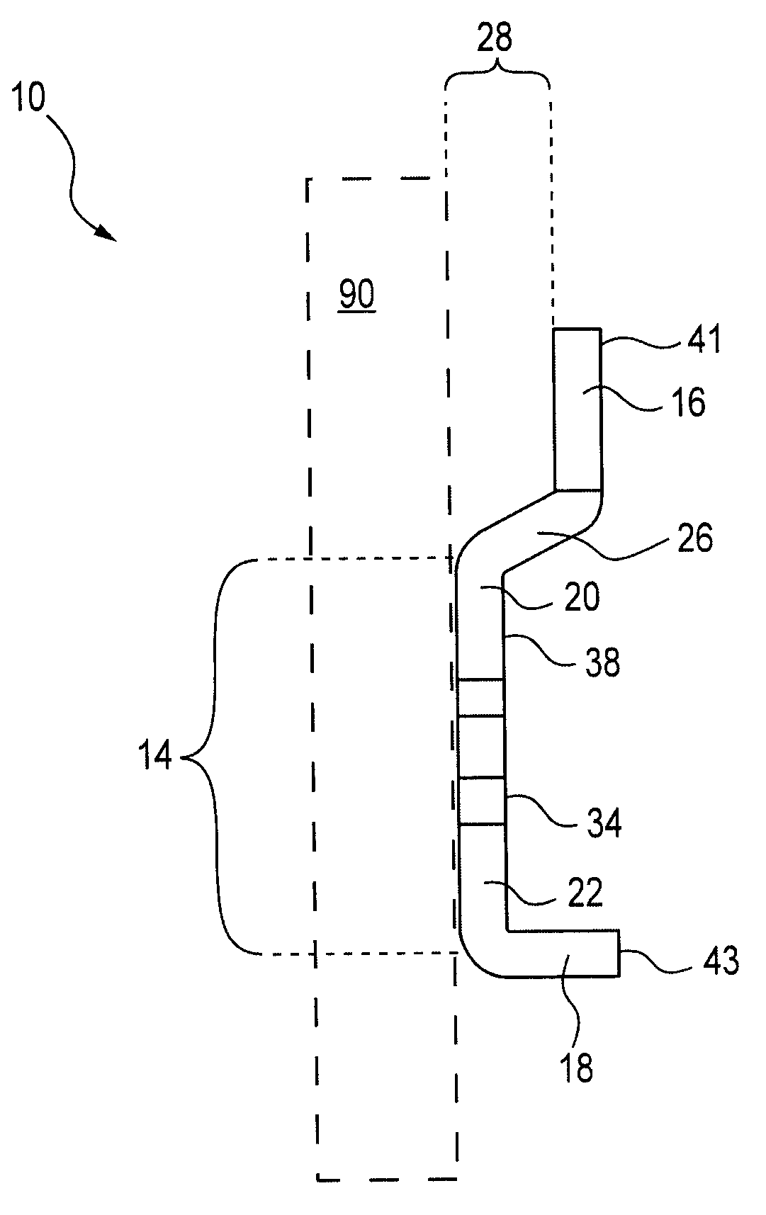
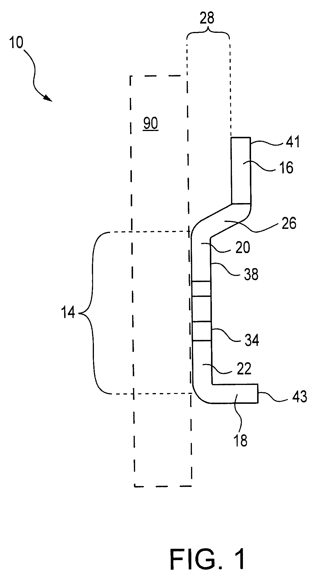
[0019]Referring to the drawings, and first to FIG. 1, a transverse cross-section of the present invention is shown. A mounting rail 10, in accordance with a preferred embodiment of this invention, is constructed of a durable material. The material may include a light weight metal, such as aluminum, or a more robust metal like steel or iron. The material may also be made of a metallic alloy, plastic, wood, or any other suitably stiff material.

[0020]The mounting rail 10 is secured to a wall with fasteners through a plurality of apertures 34, which run through the wall anchor plate 14. Preferred fasteners include screws, nails, and rivets (not shown in the figures). A combination of adhesives and fasteners, such as screws and nails, may also be used for securing the mounting rail 10 to a wall. The mounting rail 10 is comprised of a wall anchor plate 14 disposed between and integral with a hook section 16 and a support section 18. The wall anchor plate 14 is planar and rests flush again...


PUM


Abstract

A wall furniture mounting device includes an elongated mounting rail having a wall anchor plate, with a plurality of apertures, a hook section, and a support section. The plurality of apertures is configured into a pattern so that each aperture is uniquely identifiable quickly via visual inspection. The pattern repeats along the mounting rail at an interval equal to the distance between wall studs.

Description

FIELD OF THE INVENTION[0001]This invention includes a mounting rail and corresponding method for installing and leveling wall furniture (e.g., shelving, cabinetry, closet organizers, and the like) quickly. The invention greatly simplifies ensuring that shelves, cabinets, modular units, and other wall furniture is both level and securely fixed to the wall studs.DESCRIPTION OF THE PRIOR ART[0002]Wall-mounted furniture, such as cabinets, shelves, modular closet organizers, and the like, are common solutions for creating additional storage space in most construction projects. In addition to its functionality, wall furniture also adds beauty to kitchens, bathrooms, closets, and the like. As noted in U.S. Pat. No. 2,521,134, it is absolutely critical that the wall furniture be arranged in rows that are in strict horizontal alignment. Misalignment is immediately perceptible and very unsightly. Likewise, it is also critical that wall furniture be securely mounted to the wall via the wall st...

Claims


Application Information

Patent Timeline
Patent Type & Authority Applications(United States)
IPC IPC(8): A47F5/00
CPCA47B96/067A47B95/008
Inventor MERTENS, JOHN J.
Owner GRASS AMERICA
Learn More