
Earthquake resisting design method on the basis of PC binding articulation construction method

a technology of pc binding and construction method, which is applied in the direction of shock-proofing, building components, building repairs, etc., can solve the problems of loss of cross section of the column itself, deformation of the reinforcement rod, and inability to repair, so as to achieve the effect of reducing deformation and superior effects

Active Publication Date: 2015-11-19
KUROSAWA CONSTR CO LTD
View PDF0 Cites 16 Cited by
  • Summary
  • Abstract
  • Description
  • Claims
  • Application Information

AI Technical Summary

Benefits of technology

The patent text describes various known technologies for designing structures to withstand earthquakes. However, each has its limitations. The first technology uses reinforcement rods that bear the brunt of the deformation caused by the earthquake, but the large deformation energy cannot be repaired. The second technology provides a resilient member to absorb energy, but repeated earthquake forces can still cause damage and breakage of the unbonded prestressing tendon. The third technology uses a horizontal resistance member to absorb energy, but it is not designed to support the end portion of the beam and can lead to fracture of the unbonded prestressing tendon. The fourth technology uses a combination of a resilient member and a horizontal resistance member, but the horizontal resistance member cannot be repaired after the earthquake. The current design standard in Japan allows for damage to structures with a seismic intensity of 5 or higher, and there is a need for a new design method that can withstand greater earthquake disasters.

Problems solved by technology

However, this has a problem that energy is absorbed by a plastic deformation of the reinforcement rods in the same manner as the RC design of the related art, and hence the residual deformation of the reinforcement rods after the earthquake is large, and cannot be repaired.
However, it is apparent that providing a plurality of notched depressions for mounting the resilient members on a plurality of side surfaces of the column at the same level makes loss of cross section of the column itself, and thereby reduces significantly the strength thereof.
And this has a problem that because of lack of a member configured to support the end portion of the beam, repeated earthquake forces cause downward slippage at the junction to the column, which may easily cause fracture of the unbonded prestressing tendon itself and breakage of a binding junction between the beam and the column, and thereby produces a very high risk of destruction of the construction.
However, this has a problem that the fixation of the unbonded prestressing tendon in this case is 80% of a standard yield load of the prestressing tendon from the description saying “not specifically new, and is implemented by a method described in a PC standard of Architectural Societies,” in the same manner of the second known technology, repeated earthquake forces cause downward slippage at the junction to the column because there is no member configured to support the end portion of the beam, and thereby there is a very high risk of destruction of the construction caused by the fracture of the prestressing tendon.
However, it is still the plastic design as conventional, and hence the plastically deformed horizontal resistance member cannot be repaired.
Therefore, all the horizontal resistance members need to be replaced after the earthquake, which requires troublesome task in field work, so that there is a problem of significant increase in cost.

Method used


Image

  • Earthquake resisting design method on the basis of PC binding articulation construction method
  • Earthquake resisting design method on the basis of PC binding articulation construction method
  • Earthquake resisting design method on the basis of PC binding articulation construction method

Examples


Embodiment Construction

[0056]An earthquake resisting design method on the basis of a PC binding articulation construction method according to the present invention will be described in detail, based on an illustrated embodiment.

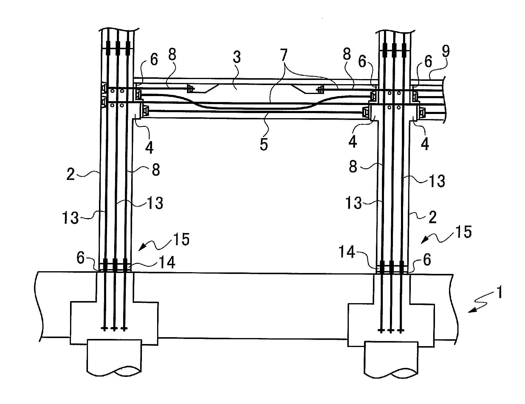
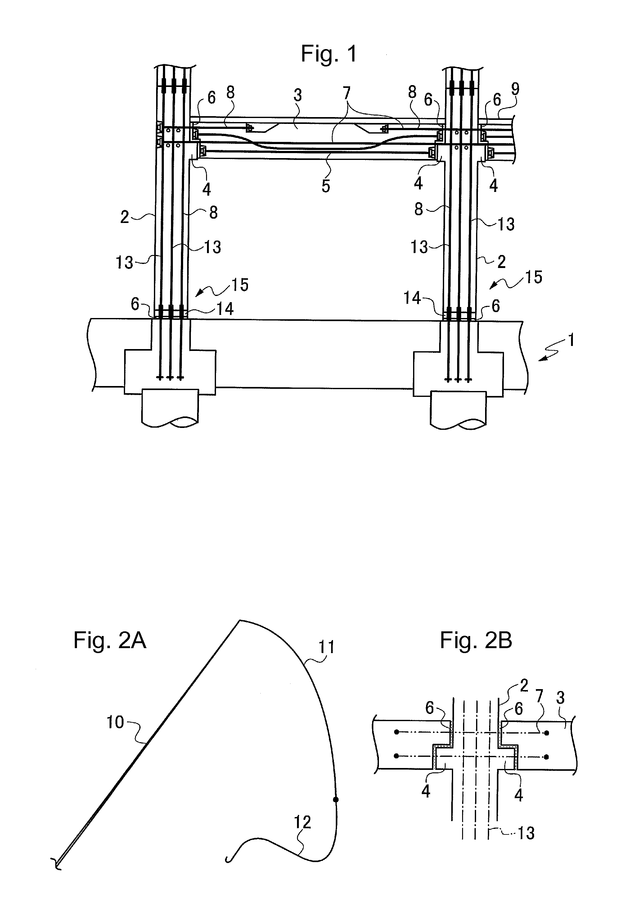
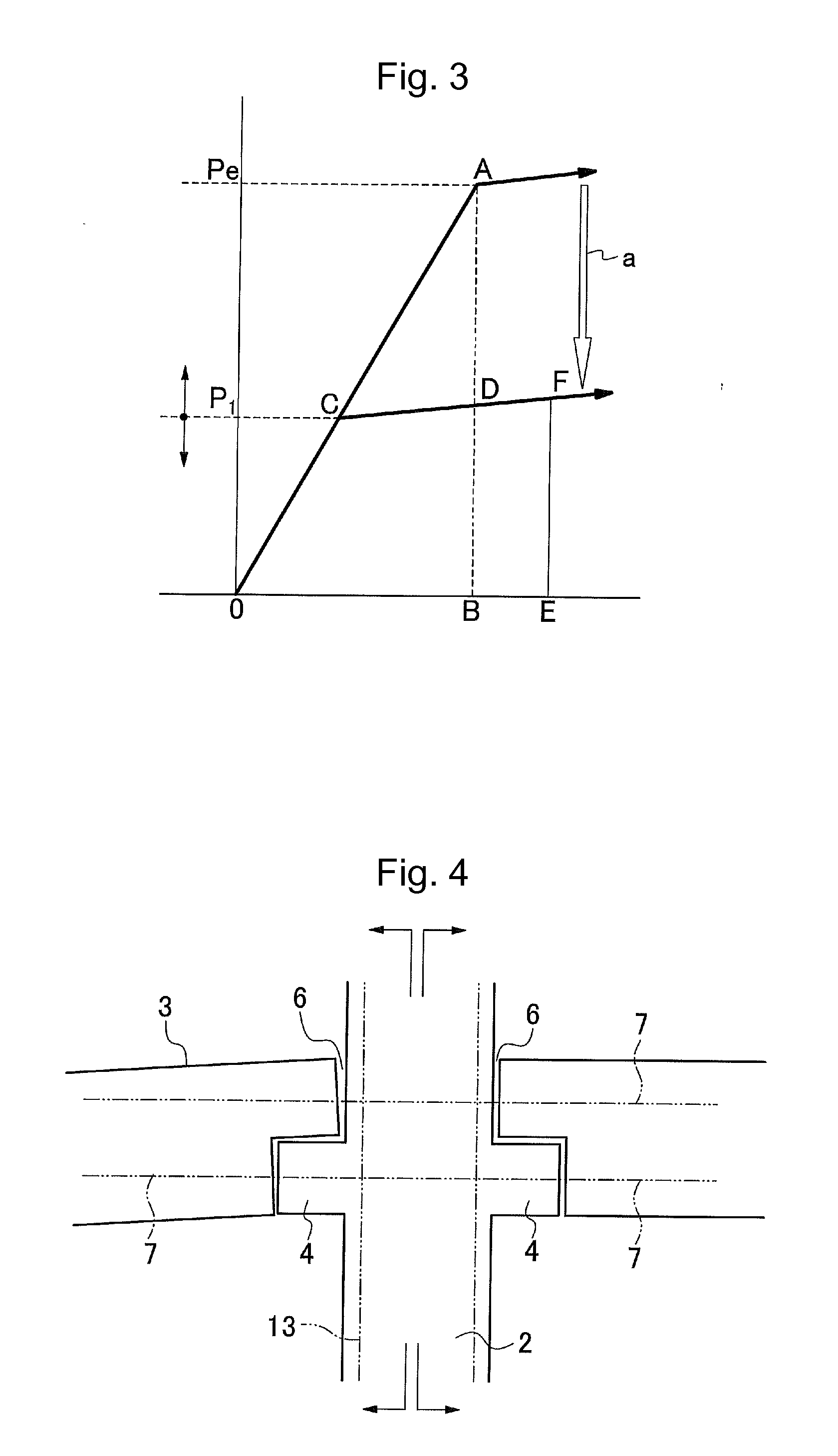
[0057]As illustrated in FIG. 1, a basic configuration of a building by the PC binding articulation construction method is a rigid frame structure including a foundation 1, columns 2, and beams 3. The columns 2 and the beams 3, which are construction members, are high-strength precast prestressed concrete members. A base block 14, to be worked as a column base, is installed between the foundation 1 and each of the columns 2 of the lowest stage. A binding joint 6 (a binding joint portion) is provided under the base block 14. A prestressing tendon 13 (a second secondary prestressing tendon) is disposed to penetrate through the foundation 1, the base block 14, and the column 2. The prestressing tendon 13 joins the foundation 1, the base block 14, and the column 2 integrally by binding ...


PUM


Abstract

In an earthquake resisting design method of a PC construction, a column and a beam, which are high-strength precast prestress concrete members, is joined by binding juncture with a prestressing tendon. A grout is filled and bonded. A first stage linear resilient design is employed, where all construction members are not damaged, for earthquakes up to a predetermined earthquake load design value. A second stage linear resilient design is employed, where earthquake energy is absorbed by breakage of the bond of the grout, and principal construction members are not damaged, for earthquakes exceeding the predetermined earthquake load design value. By employing a non-linear resilient design in which the first stage linear resilient design and the second stage linear resilient design is combined, an earthquake-resisting design level is significantly increased, the construction can resist earthquakes exceeding a seismic intensity 6 upper.

Description

BACKGROUND OF THE INVENTION[0001]1. Field of the Invention[0002]The present invention relates to an earthquake resisting design method of a prestressed concrete construction (hereinafter, referred to as “PC construction”). The PC construction of the present invention is defined to indicate a configuration in which high-strength precast prestressed concrete (PCaPC) members (column, beam) are joined by PC binding juncture with a prestressing tendon.[0003]2. Description of the Related Art[0004]A reinforced concrete construction (RC construction) of the related art, being inexpensive, highly rigid and superior in occupant comfort, is used in buildings such as collective housing and offices in many cases.[0005]In contrast, a prestressed concrete construction (PC construction) is configured to resist an envisioned load by applying a prestress to a cross section of a concrete member in advance so as to be applied to buildings having a large span beam or beams and columns that support a hea...

Claims


Application Information

Patent Timeline
Patent Type & Authority Applications(United States)
IPC IPC(8): E04H9/02E04C5/01E04C3/34E04B1/98E04H12/16
CPCE04H9/021E04B1/98E04H9/02E04C5/012E04H12/16E04C3/34E04H9/025E04B1/22
Inventor KUROSAWA, RYOHEI
Owner KUROSAWA CONSTR CO LTD
Learn More