Eureka AIR delivers breakthrough ideas for toughest innovation challenges, trusted by R&D personnel around the world.

Method and system for reducing motion sickness in virtual reality ride systems

a virtual reality and ride technology, applied in the field of virtual reality ride systems, can solve the problems of visual induced motion sickness, motion sickness in many users, and inability so as to reduce the effect of motion sickness

Active Publication Date: 2015-11-12
DREAMWORKS ANIMATION LLC
View PDF4 Cites 50 Cited by
  • Summary
  • Abstract
  • Description
  • Claims
  • Application Information

AI Technical Summary

Benefits of technology

This patent describes a virtual reality ride system that can reduce motion sickness associated with virtual reality experiences. The system includes a dynamic platform that vibrates at a low frequency, which is detected by the rider's vestibular system. This "virtual reality sickness" can be caused by the visual and vestibular systems becoming disconnected in the virtual environment. By adding these low-frequency vibrations to the movements and visual cues of the virtual environment, the system can make the virtual world feel less real and more grounded on the rider's location in the real world. This technology can be used in virtual reality headsets and rider platforms for a more immersive virtual reality experience.

Problems solved by technology

Although virtual reality systems may provide a realistic and immersive experience, they also cause motion sickness in many users.
Motion sickness may occur when the systems of the body responsible for balance do not agree with each other.
A person may experience visually induced motion sickness when, for example, viewing a first-person perspective of a moving scene, such as in a video game or a flight simulator.
Moreover, motion sickness may be even more severe during a virtual reality experience in which all external reference points that could provide a frame of reference are blocked from vision and the simulated images are 3D, such as when a 3D headset is used.

Method used


Image

  • Method and system for reducing motion sickness in virtual reality ride systems
  • Method and system for reducing motion sickness in virtual reality ride systems
  • Method and system for reducing motion sickness in virtual reality ride systems

Examples


Embodiment Construction

[0028]The following description sets forth specific configurations, parameters, and the like. It should be recognized, however, that such description is not intended to limit the present disclosure, but is instead provided as a description of exemplary embodiments.

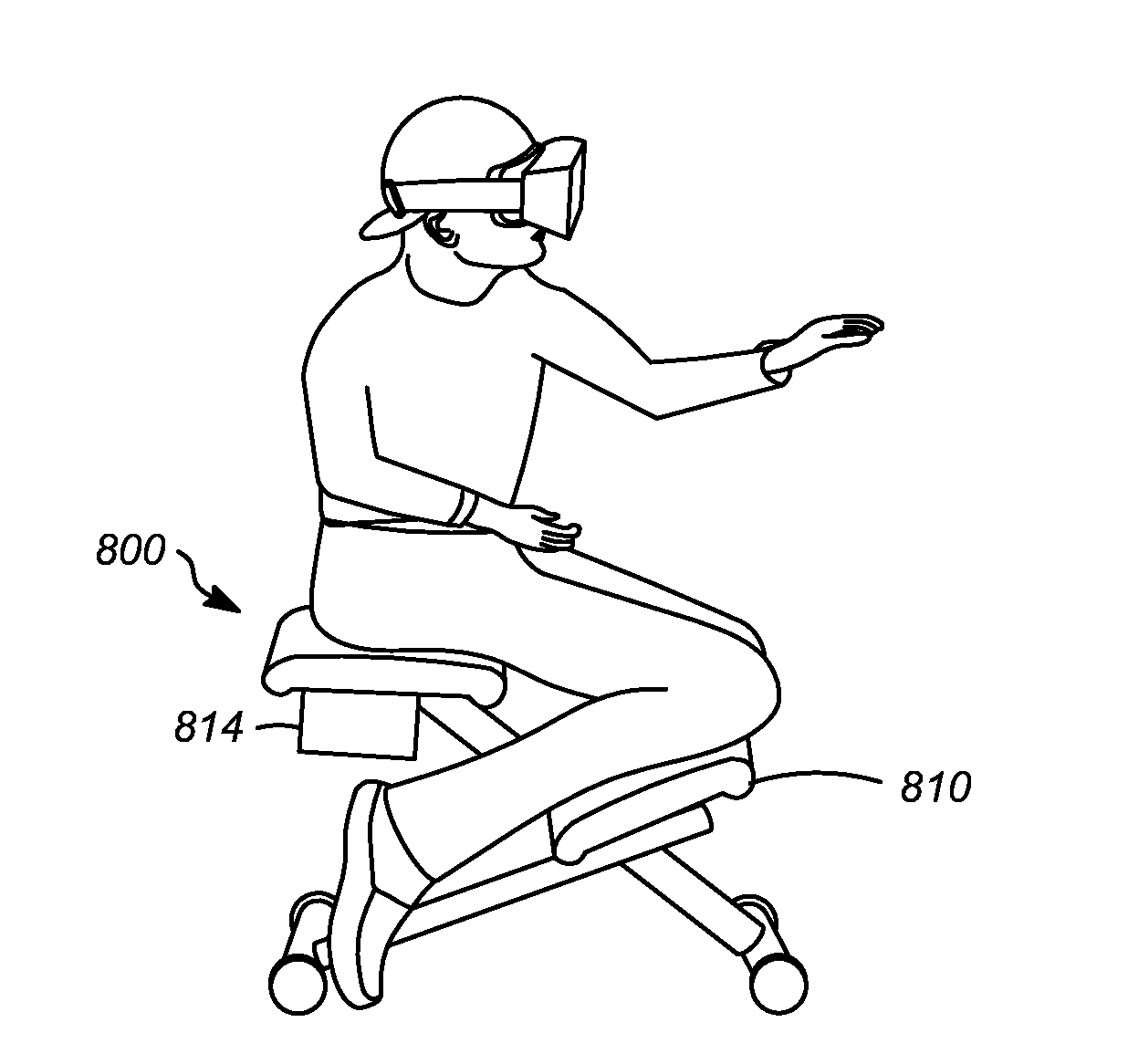
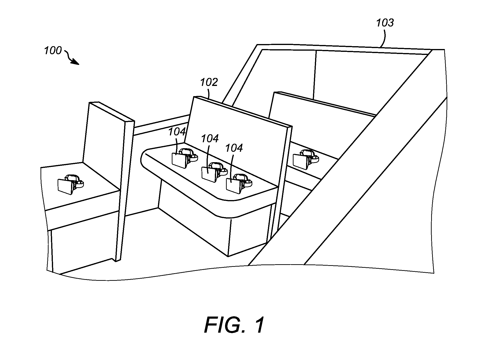
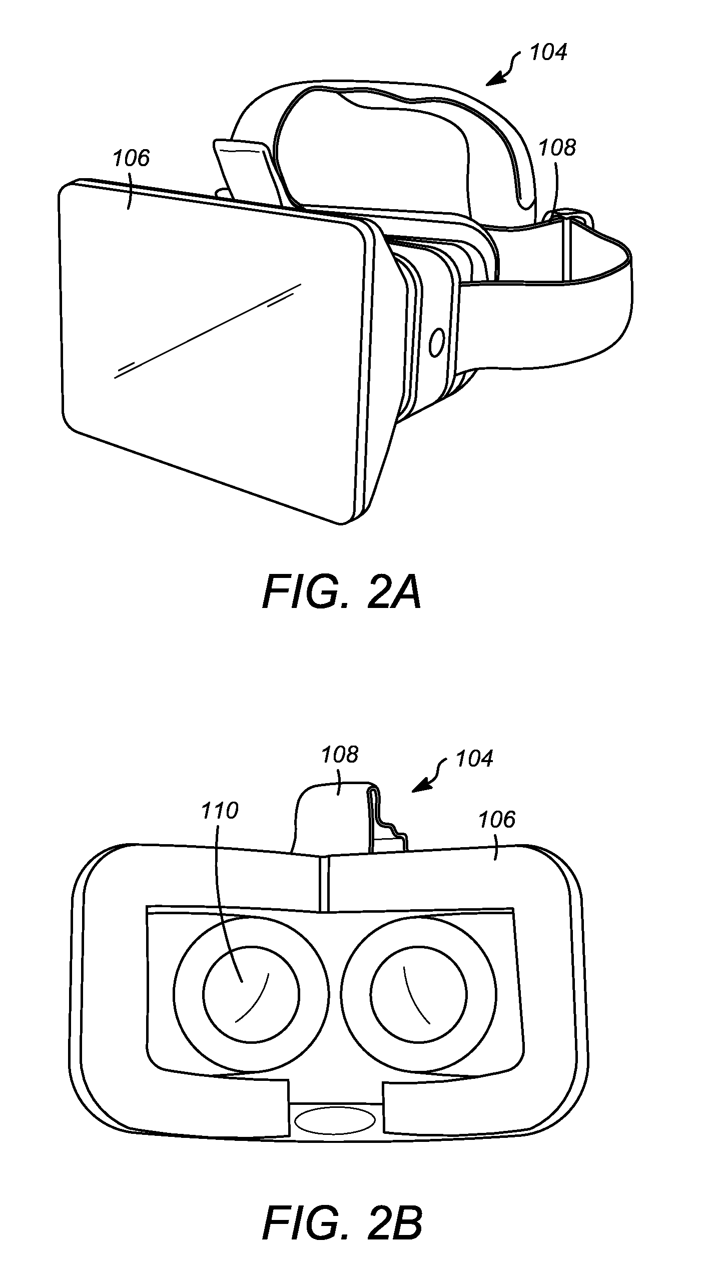
[0029]FIG. 1 depicts an embodiment of a virtual reality ride system 100 including dynamic platform 102 and virtual reality headsets 104. Each headset 104 displays a video image, which may include, for example, a video of an animated virtual environment. The dynamic platform 102 may move to provide physical sensations associated with the visual events occurring in the virtual environment seen by the rider. A surrounding structure 103 may include walls, doors, windows, lights, or other features associated with the type of virtual reality ride. For example, a ride showing a virtual flight may have a structure resembling an airplane. In addition, virtual reality ride system 100 may provide audio to accompany the visual imagery...


PUM


Abstract

A virtual reality ride system including a headset, a control unit, and a dynamic platform. The headset includes a display unit configured to display a video of an animated virtual environment. The control unit includes one or more processors configured to perform render processing that renders the video of the virtual environment; event motion processing that generates first data representing motions associated with events in the virtual environment; and low-frequency motion processing that generates second data representing low-frequency vibrations unrelated to the events in the virtual environment. The dynamic platform is configured to produce the motions associated with the events in the virtual environment based on the first data, and to produce the low-frequency vibrations based on the second data. The low-frequency vibrations include a frequency between about 5 Hz and 70 Hz.

Description

CROSS-REFERENCE TO RELATED APPLICATIONS[0001]This application claims the benefit of U.S. Provisional Application No. 61 / 991,358, filed May 9, 2014, which is hereby incorporated by reference in its entirety.BACKGROUND[0002]1. Field[0003]This application relates generally to virtual reality ride systems, and, more specifically, to methods and systems using low-frequency vibrations to reduce motion sickness caused by virtual reality.[0004]2. Description of the Related Art[0005]Virtual reality is a computer-simulated environment that can simulate a user's physical presence in real or imaginary environments. A virtual reality environment may include visual images displayed either on a computer screen or through a stereoscopic (e.g., 3D) display, such as a wearable headset. The virtual reality environment may also include sound provided through speakers or headphones and force feedback via, for example, a dynamic platform or a vibrating controller or joystick. Applications of virtual real...

Claims


Application Information

Patent Timeline
Patent Type & Authority Applications(United States)
IPC IPC(8): G06T13/00G02B27/01G06T19/00
CPCG06T13/00G02B27/017G06T19/006G06F3/016A61M2021/0022A61M21/00A61M2021/0011A61M2021/0027A61M2021/005A61M2205/332A61M2205/507A61M2205/70A63F13/25A63F13/428A63F13/211A63F13/212A63F13/28B60W40/08
Inventor HERMAN, BRAD KENNETHAKMAL, SHIRAZLAFOLLETTE, BRYN
Owner DREAMWORKS ANIMATION LLC
Why Eureka
Eureka Blog
Learn More