An active front-end rectifier filter delay compensation method based on model predictive control

a front-end rectifier and filter delay compensation technology, applied in adaptive control, complex mathematical operations, instruments, etc., can solve the problems of signal delay, high sampling frequency, affecting the operating performance, etc., to improve the control quality and robustness of the system, and effectively eliminate the filter delay impact of the mpc algorithm.

Active Publication Date: 2015-11-05
TIANJIN UNIV
View PDF3 Cites 12 Cited by
  • Summary
  • Abstract
  • Description
  • Claims
  • Application Information

AI Technical Summary

Benefits of technology

The present invention provides a method for compensating for the impact of filter delay in an active front-end rectifier control system. The method uses model predictive control, which can effectively reduce the impact of filter delay without adding additional equipment. It has been tested to work even when there is a long delay in the system. The method compensates for the impact of filter delay by inputting the observed input current values into the model predictive control algorithm, resulting in optimal switching state and corresponding input voltage values. This method improves control quality and robustness, enhancing the effectiveness of the actual MPC application, and ensures stable operation of the active front-end rectifier in the presence of long delays.

Problems solved by technology

For eliminating interference, filtering process should be performed to the detected voltage and current signal prior sampling, but the filter will create signal delay while filtering high-frequency interference signal.
As the MPC adopts circulation for optimization and non-constant-frequency control mode of outputting directly without modulation, the MPC has the advantage of fast transient response speed, but also has the disadvantages of high sampling frequency, and the system delay, thus affecting the operating performance.
When the cut-off frequency of filter is low, signal filtering will suffer from some delay and produce variation between actual output value and set value of system, and further will impact the control effect.

Method used


Image

  • An active front-end rectifier filter delay compensation method based on model predictive control
  • An active front-end rectifier filter delay compensation method based on model predictive control
  • An active front-end rectifier filter delay compensation method based on model predictive control

Examples


Embodiment Construction

[0023]The present invention will be described in detail in combination with the accompanying embodiments.

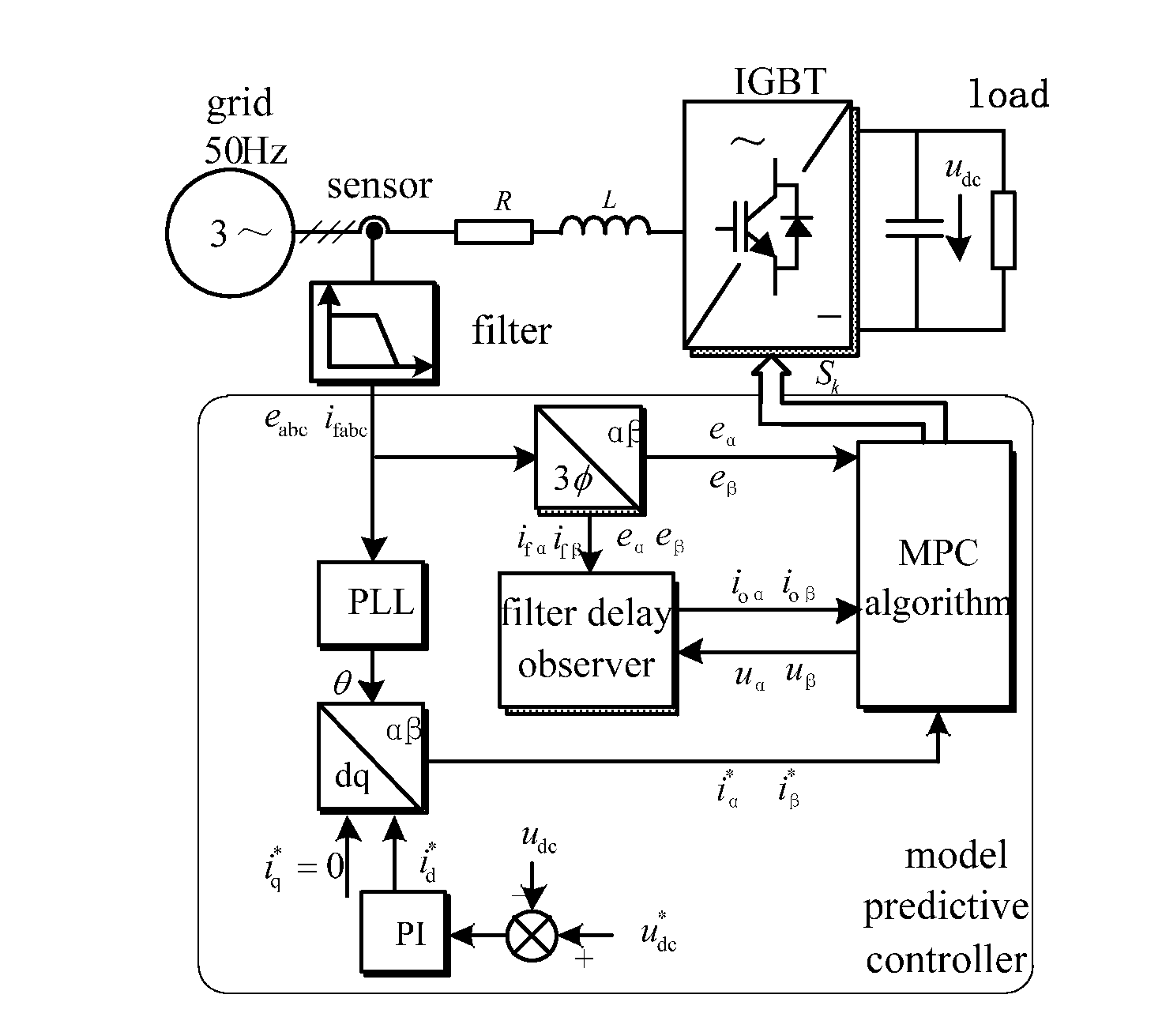
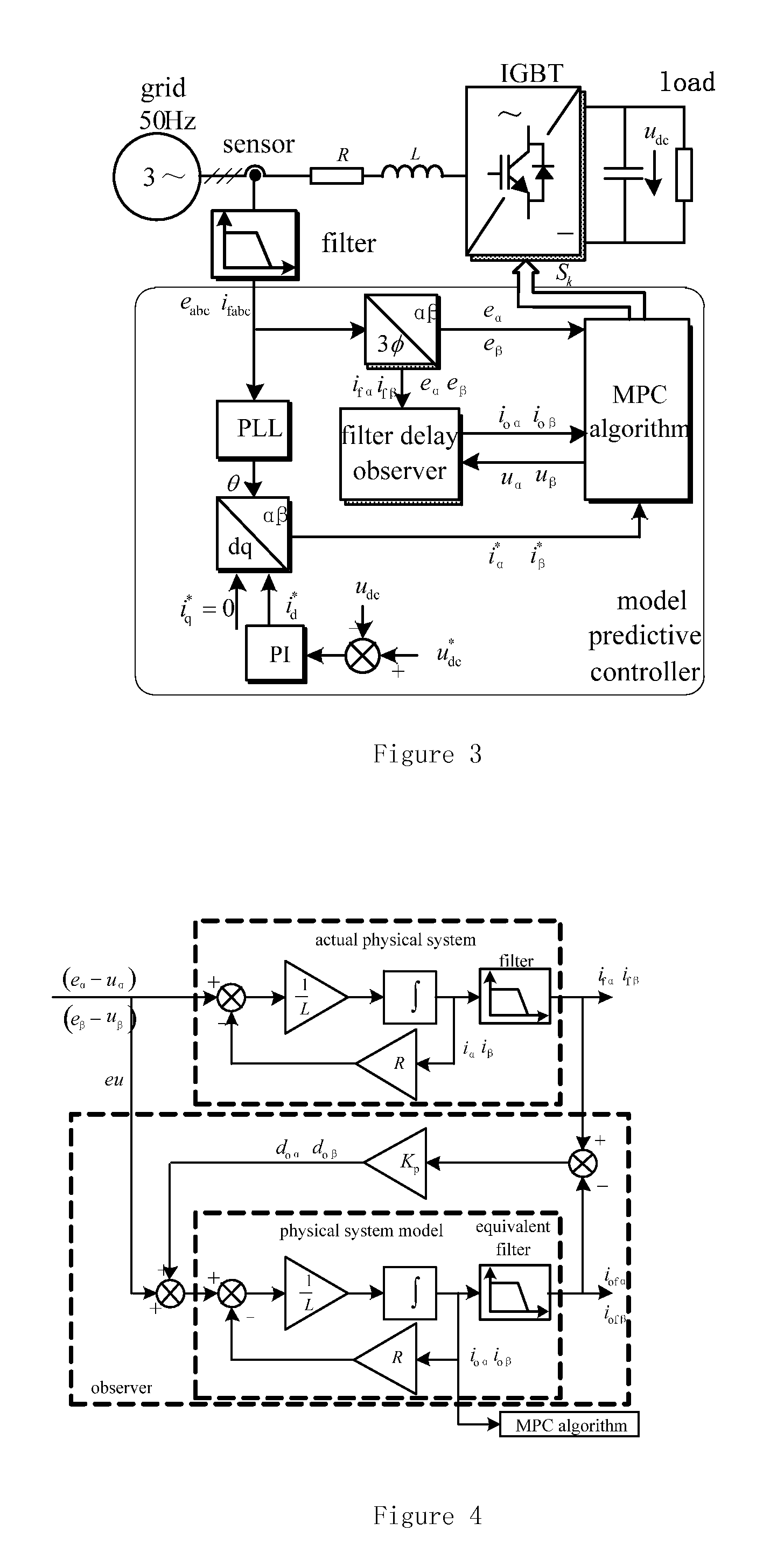
[0024]A filter delay compensation method for an active front-end rectifier based on model predictive control, includes the following steps:

[0025]Step 1: detecting a three-phase grid voltage and three-phase input current sampling values of an active front-end rectifier, and transforming both via Clarke transformation to acquire grid voltage sampling values eα and eβ, and input current sampling values ifα and ifβ under a two-phase stationary coordinate system;

[0026]Step 2: establishing an equivalent mathematical model of rectifier on the basis of the voltage balancing equation (1) in an actual rectifier;

{eα=uα+Riα+Liαteβ=uβ+Riβ+Liβt(1)

[0027]wherein, eα and eβ are grid voltage sampling values, iα and iβ are input current values of the rectifier; L and R are input inductance values and equivalent series resistance value respectively; uα and uβ are input voltage values of rectifier;

[0...


PUM


Abstract

An active front-end rectifier filter delay compensation method based on model predictive control is disclosed. The method includes following steps: detecting a three-phase grid voltage and three-phase input current sampling value of an active front-end rectifier, and transforming both via Clarke transformation to acquire grid voltage sampling values eα and eβ, and input current sampling values ifα and ifβ under a two-phase stationary coordinate system; establishing an equivalent mathematical model of rectifier on the basis of voltage balancing equation (1) in an actual rectifier, and establishing an equivalent filter model on the basis of a transfer function corresponding to the actual filter, thus constituting a filter delay observer; and, compensating the difference value between the input current sampling values ifα and ifβ, and equivalent current sampling values iofα and iofβ into an input of the filter delay observer via a proportional controller. In comparison to the input current sampling values ifα and ifβ, the input current observed values ioα and ioβ of the rectifier are not impacted by a filter latency and are closer to the actual input current value of the rectifier such that the impact of the filter delay is compensated.

Description

FIELD OF THE INVENTION[0001]The present invention relates to a filter delay compensation method for an active front-end rectifier based on model predictive control, and belongs to the technical field of power electronic control.BACKGROUND OF THE INVENTION[0002]The power convertor all-digital control method based on model predictive control has grown rapidly in recent years. MPC (Model predictive control) is a mathematical-model-based control algorithm used for predicting the future response of object to be controlled. The algorithm comprises a value function defined according to the object to be controlled. By minimizing the value function, the optimal voltage vector is obtained for the algorithm during each sampling-period according to sampling-period prediction, and the optimal voltage vector is regarded as the interaction vector for the next period. MPC belongs to a non-linear control technique, and has fast transient response speed due to its no inclusion of linear controller an...

Claims


Application Information

Patent Timeline
IPC IPC(8): G05B13/04G06F17/14
CPCG06F17/14G05B13/048H02J3/1842G06F17/13Y02E40/20H02M7/219H02M1/0009
Inventor XIA, CHANGLIANGLIU, TAOSONG, ZHANFENG
Owner TIANJIN UNIV
Why Eureka
Try Eureka