
Endpoint determination for capillary-assisted flow control

a technology of endpoint determination and flow control, which is applied in process control, semiconductor/solid-state device testing/measurement, instruments, etc., can solve the problems of severe economic disadvantage of the process system and the force shutdown of the implant tool

Active Publication Date: 2015-10-29
ENTEGRIS INC
View PDF0 Cites 1 Cited by
  • Summary
  • Abstract
  • Description
  • Claims
  • Application Information

AI Technical Summary

Benefits of technology

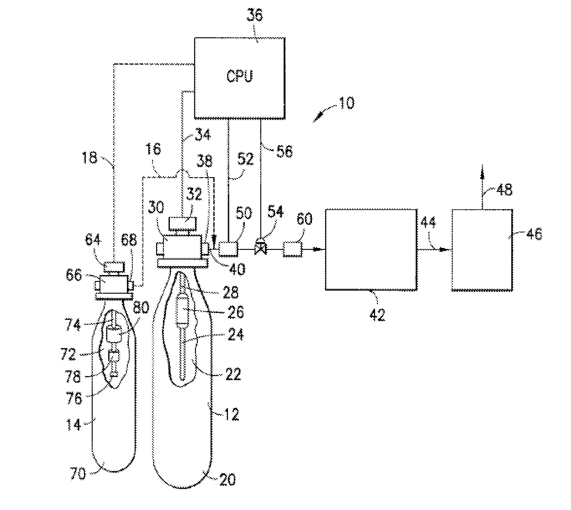
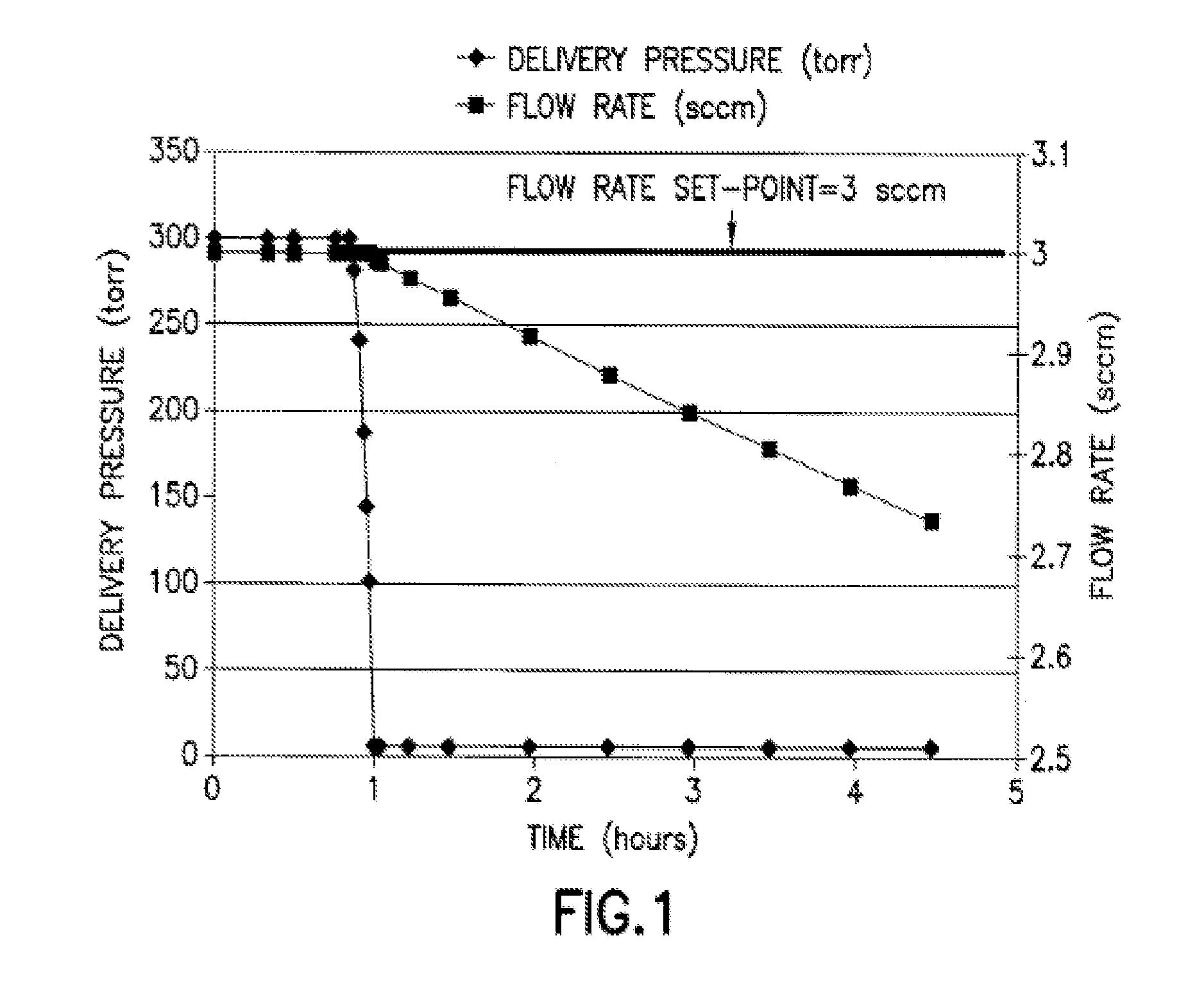
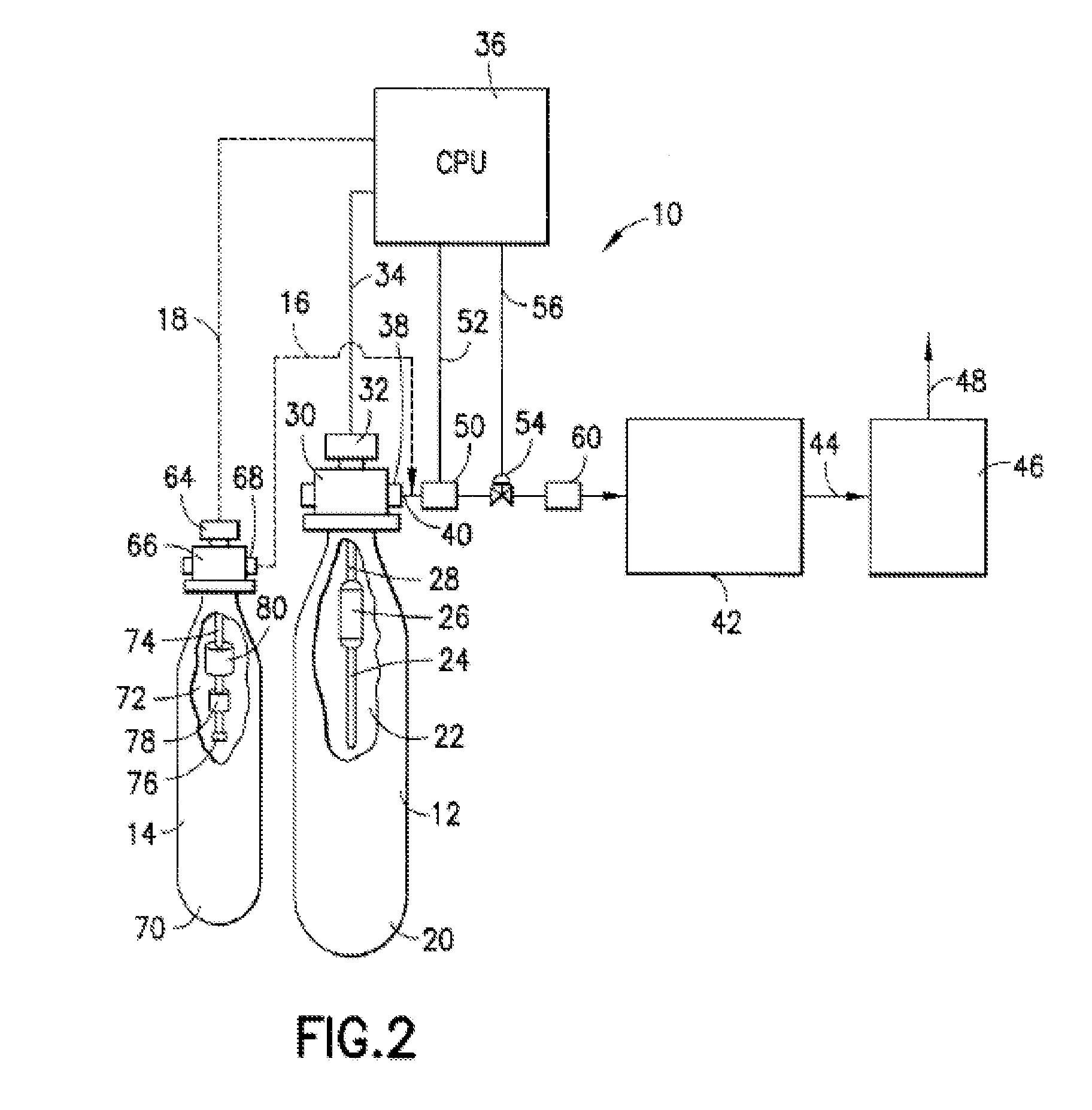
The present invention relates to a method and apparatus for controlling the endpoint of fluid flow in a fluid supply vessel. The method involves selectively establishing fluid flow, controlling fluid flow through a flow passage disposed in the interior volume of the fluid supply vessel with a static flow restricting device and a selectively actuatable valve element, and monitoring at least one characteristic of the fluid supply vessel or the fluid dispensed therefrom to determine the endpoint. The apparatus includes a monitoring unit and a CPU operatively linked in output signal receiving relationship to the monitoring unit, with endpoint condition information stored in the CPU. The invention also includes a fluid supply system comprising a fluid supply vessel, first flow circuitry, and second flow circuitry, optionally with a buffering reservoir, pressure regulator, pressure transducer, and mass flow controller. The technical effects of the invention include improved control of fluid flow and improved accuracy in determining the endpoint of fluid supply.

Problems solved by technology

Any sudden unanticipated exhaustion of the dopant fluid supply during tool operation will force shutdown of the implant tool, and require discarding or rework of wafers then in process, as well as delay in operation as a fresh fluid supply vessel is installed to replace the fluid-depleted vessel.
Such sudden unanticipated exhaustion of the fluid supply and the operational dislocations attending same pose a severe economic disadvantage to the process system.
This problem is relevant to the use of fluid supply vessels employing capillary-assisted flow control of the supplied fluid.

Method used


Image

  • Endpoint determination  for capillary-assisted flow control
  • Endpoint determination  for capillary-assisted flow control
  • Endpoint determination  for capillary-assisted flow control

Examples


Embodiment Construction

[0018]The present disclosure relates to endpoint determination for capillary-assisted flow control, such as may be used for supplying fluid to a semiconductor manufacturing tool such as an ion implanter.

[0019]The endpoint determination may be carried out in a method including: selectively establishing fluid flow from a fluid supply vessel; controlling fluid flow through a flow passage disposed in an interior volume of the fluid supply vessel with a static flow restricting device, e.g., a capillary device, and a selectively actuatable valve element upon establishing fluid flow; and monitoring a characteristic of the fluid supply vessel or a fluid supplied therefrom to determine the endpoint, wherein the static flow restricting device and the selectively actuatable valve element are arranged along the flow passage.

[0020]The static flow restricting device may comprise one or more capillary type or flow throttling passages. For example, the flow restricting device can include two or mor...


PUM


Abstract

Apparatus and method for determining endpoint of a fluid supply vessel in which fluid flow is controlled through a flow passage disposed in an interior volume of the fluid supply vessel with a static flow restricting device and a selectively actuatable valve element upon establishing fluid flow. The endpoint determination can be employed to terminate fluid supply from the fluid supply vessel and / or to switch from a fluid-depleted supply vessel to a fresh vessel for continuity or renewal of fluid supply operation. The apparatus and method are suitable for use with fluid-utilizing apparatus such as ion implanters.

Description

CROSS-REFERENCE TO RELATED APPLICATIONS[0001]This is a continuation under 35 USC 120 of U.S. patent application Ser. No. 13 / 704,612 filed Dec. 15, 2012 in the names of Joseph D. Sweeney, et al. for “ENDPOINT DETERMINATION FOR CAPILLARY-ASSISTED FLOW CONTROL,” which in turn is a national phase under 35 U.S.C. §371 of International Patent Application PCT / US2011 / 041013 filed Jun. 18, 2011 in the names of Joseph D. Sweeney, et al. for “ENDPOINT DETERMINATION FOR CAPILLARY-ASSISTED FLOW CONTROL,” which in turn claims the benefit of priority under 35 USC 119 of U.S. Provisional Patent Application No. 61 / 356,451 filed Jun. 18, 2010 in the names of Joseph D. Sweeney, et al. for “ENDPOINT DETERMINATION FOR CAPILLARY-ASSISTED FLOW CONTROL,” and U.S. Provisional Patent Application No. 61 / 366,523 filed Jul. 21, 2010 in the names of Joseph D. Sweeney, et al. for “ENDPOINT DETERMINATION FOR CAPILLARY-ASSISTED FLOW CONTROL.” The disclosures of U.S. Patent Application No. 13 / 704,612, International ...

Claims


Application Information

Patent Timeline
Patent Type & Authority Applications(United States)
IPC IPC(8): F17D3/01
CPCF17D3/01H01L21/67017H01L21/67253G05D7/0635H01J37/3171H01J2237/006H01J2237/30466Y10T137/86389Y10T137/0324F17D3/00H01L22/30
Inventor SWEENEY, JOSEPH D.AVILA, ANTHONY M.WODJENSKI, MICHAEL J.DESPRES, JOSEPH R.BAUM, THOMAS H.
Owner ENTEGRIS INC
Learn More