
Advanced Stranded Cable Termination Methods and Designs

a technology of stranded cables and termination methods, applied in the direction of cables, belts/chains/gearings, mechanical equipment, etc., can solve the problems of difficult organization, low efficiency, and difficult handling of synthetic filaments, and achieve the effect of shortening the length required

Active Publication Date: 2015-10-22
BRIGHT TECH CO LTD
View PDF28 Cites 17 Cited by
  • Summary
  • Abstract
  • Description
  • Claims
  • Application Information

AI Technical Summary

Benefits of technology

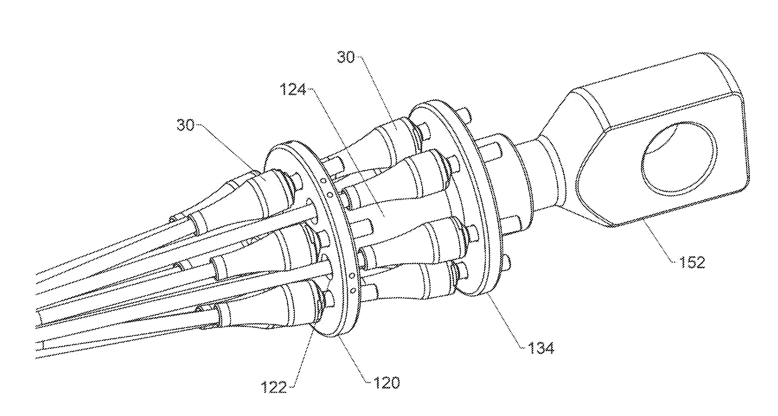
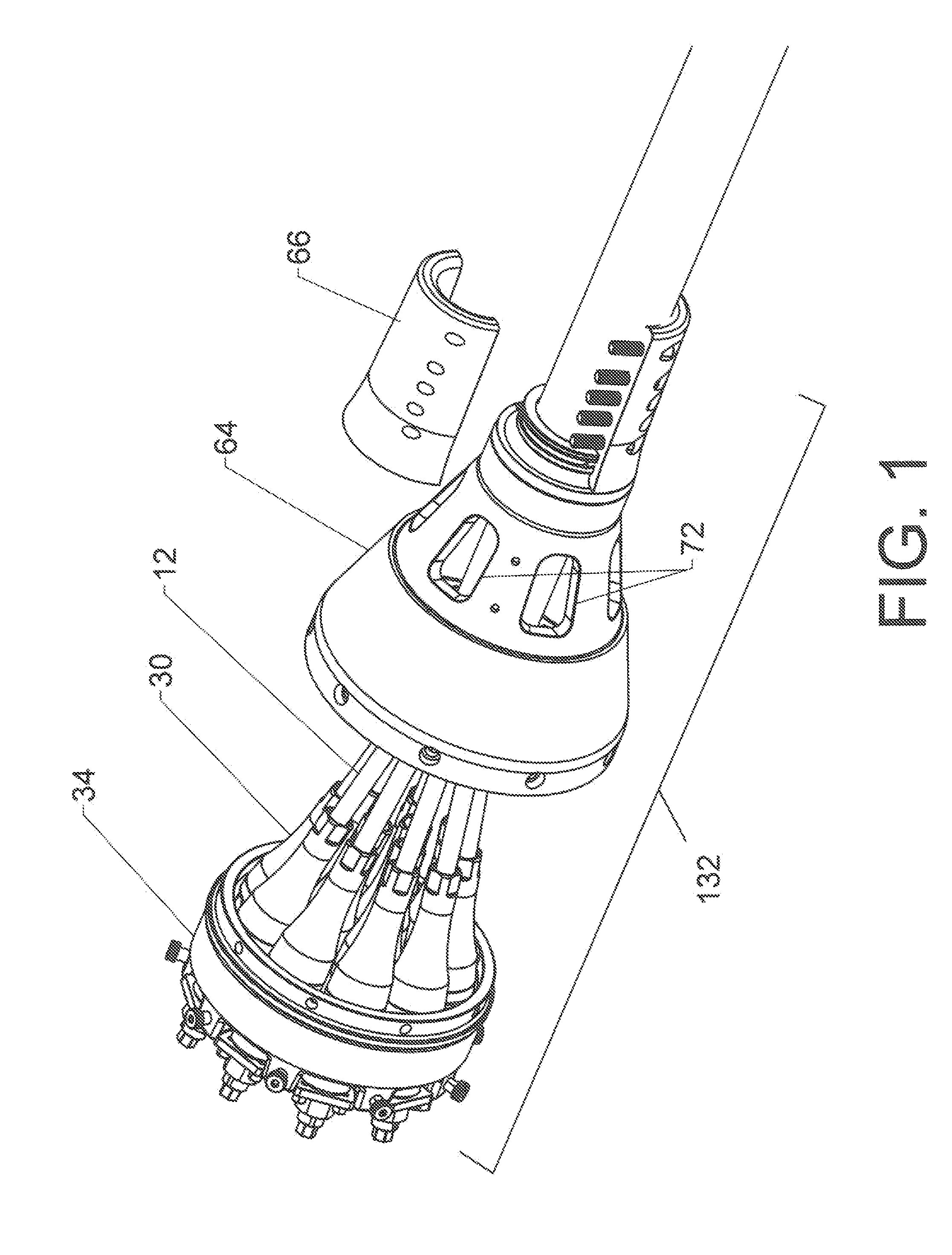
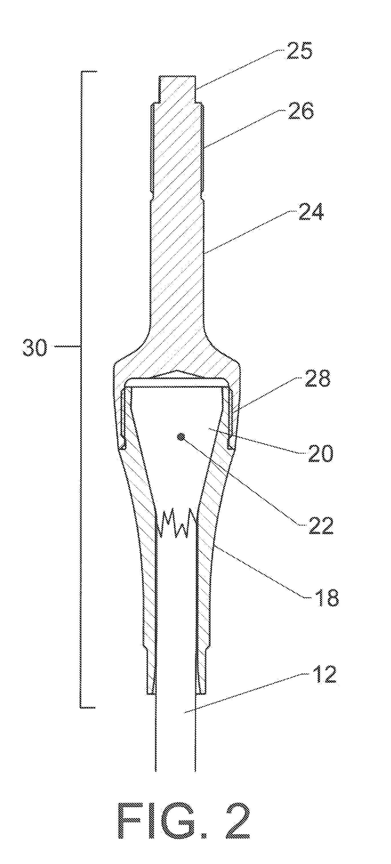
The present invention provides components that allow for a compact overall termination of a multi-stranded synthetic filament cable and the inspection of individual components. The cable is made up of multiple individual strands, each with a termination on their free end. These termination are connected to a collector to form an overall cable termination. The invention also includes an advanced collar that helps to make the transition from the collector to the free portion of the cable more efficient, reducing the length of the cable.

Problems solved by technology

The filaments are very strong in tension, but they are not very rigid.
These facts make such synthetic filaments difficult to handle during the process of adding a termination and difficult to organize.
While the invention could in theory be applied to older cable technologies—such as wire rope—it likely would offer little advantage and the additional time and expense of implementing the invention would not be worthwhile.

Method used


Image

  • Advanced Stranded Cable Termination Methods and Designs
  • Advanced Stranded Cable Termination Methods and Designs
  • Advanced Stranded Cable Termination Methods and Designs

Examples


example one

12 Strand

[0096]Synthetic cables having twelve individual strands are common. When braided, this construction includes six strands helically wound in a first direction and six strands helically woven in the opposite direction. The two groups are interwoven. Twelve strand cables are also made with parallel strands.

[0097]Several different strand groupings are possible for a twelve strand cable. The first variation will be referred to as a “12×1 collection pattern.” This groups the 12 strands in a circular cross section. This design aligns both “S” and “Z” twist strands and matches the natural construction (which is a hollow circle). The “12×1” structure is highly balanced but does tend to produce a fairly large expansion in cross-section as the strand terminations are added and the connections to the collector are made.

[0098]The second variation will be referred to as a “9×3 collection pattern.” This arrangement includes three “core” strands in the center and nine outer strands. This c...

example two

8 Strand

[0101]Synthetic cables having eight strands are also common. When braided, this construction includes four strands helically wound in a first direction and four strands helically wound in the opposite direction. The strands are braided together. Eight-stranded cables having a parallel construction are also known. Whether braided or parallel, several idealized strand groupings are possible for such a cable.

[0102]The first variation will be referred to as an “8× collection pattern” which includes eight strands in a circular cross section. The second variation will be referred to as a “5×3 collection pattern” which wraps five outer strands around a core group of three strands. The third variation is a “4×4 collection pattern” in which two sub-groups of four strands each are created. The anticipated benefits for each of these collection pattern are generally the same as those described previously for the twelve strand variations.

[0103]This disclosure encompasses several differen...


PUM


Abstract

Advanced components that are useful in providing a compact overall cable termination for a multi-stranded cable and in providing for the control and inspection of the individual components of a multi-stranded cable. Multiple individual cable strands are provided with a termination on their free end. These terminations are connected to a collector. An advanced collar is provided that assists in the transition of the strands as they leave the collector and transition to the structure found in the free portion of the cable.

Description

CROSS-REFERENCES TO RELATED APPLICATIONS[0001]This non-provisional patent application claims the benefit of an earlier-filed provisional application. The first provisional application was assigned Ser. No. 61 / 982,825. It listed the same inventor.STATEMENT REGARDING FEDERALLY SPONSORED RESEARCH OR DEVELOPMENT[0002]Not Applicable.MICROFICHE APPENDIX[0003]Not ApplicableBACKGROUND OF THE INVENTION[0004]1. Field of the Invention[0005]This invention relates to the field of tensile strength members such as multi-stranded cables made of synthetic filaments. More specifically, the invention comprises devices and methods for creating a more compact overall cable termination, improved control over strand position and alignment, and improved inspectability.[0006]2. Description of the Related Art[0007]A cable must generally be provided with one or more end connections in order to be useful. The end connections allow the cable to carry and transmit a useful load. An end connection may be a simple...

Claims


Application Information

Patent Timeline
Patent Type & Authority Applications(United States)
IPC IPC(8): F16G11/04
CPCF16G11/046F16G11/025F16G11/042
Inventor CAMPBELL, RICHARD V.
Owner BRIGHT TECH CO LTD
Learn More