Semi-grouting sleeve assembly of precast beam steel connection of cast-in-place beam column joints and application thereof

A technology of semi-grouting sleeves and cast-in-place beams and columns, which is applied in the direction of building components, building reinforcements, structural elements, etc., can solve the problems of cost increase, tensile strength reduction, application process impact, etc., to ensure the connection Quality and safety, avoidance of length dimensions, effect of guaranteed thread quality

Pending Publication Date: 2018-07-06
浙江省建筑科学设计研究院建筑设计所
View PDF0 Cites 5 Cited by
  • Summary
  • Abstract
  • Description
  • Claims
  • Application Information

AI Technical Summary

Problems solved by technology

The first one is to use the tensile steel bars on both sides of the column to bend upwards at 90° to anchor the steel bars, and the exposed horizontal length of the steel bars should not be less than 0.4L abE , and should extend to the inner edge of the longitudinal reinforcement on the outer side of the column, the coincident length of the anchored horizontal straight section of the steel bar on both sides of the beam is greater than the section length of the column -100mm, and the number of steel bars in the horizontal straight section of the anchored steel bar at the node is doubled, according to The specification requires that the spacing of the anchoring steel bars be ≥ 25mm. If the spacing of the steel bars in the anchored horizontal straight section cannot meet the requirements of the specification, it will cause quality defects and safety problems at the joints. At the same time, it is necessary to carry out the dislocation layout design of the longitudinal reinforcement of the prefabricated beam on both sides, the design workload and the difficulty of prefabrication increase, and the degree of standardization decreases. Asymmetric quality and safety issues
The second type is that the two prefabricated beams are anchored at the cast-in-place joints of the columns with tensile steel bars and end anchor heads. The anchor heads require that the anchorage length of the beam steel bars should not be less than 0.4L abE , extending through the central axis 5d of the column, using tensile longitudinal steel bars and adding end anchor heads for anchoring. Similarly, the prefabricated beam steel bars on both sides of the column coincide with a certain length in the anchored horizontal straight line section, and the steel bars at the nodes anchor the horizontal straight line section. The number of steel bars is doubled. If the steel bar spacing or anchor head spacing of the horizontal lap section cannot meet the specification requirements, it will cause joint quality defects and safety problems. If the steel bar spacing or anchor head spacing is to be ensured, prefabrication must also be increased. The width of the beam section increases the cost. At the same time, the design of the dislocation layout of the longitudinal reinforcement of the prefabricated beam on both sides increases, the design workload and the difficulty of prefabrication increase, and the degree of standardization decreases. There will be quality and safety problems of asymmetrical reinforcement arrangement of the beam
The third type is that two prefabricated beams are connected by mechanical connection at the cast-in-place joints of the two prefabricated beams, that is, mechanical sleeve connection. The horizontal dislocation of the steel bars is not required, and the cross-sectional width of the beams does not need to be increased. However, the longitudinal steel bars at the joints are mechanically threaded. For sleeve connection, the steel bars at both ends of the connection must be accurately aligned without errors, which cannot be done on the construction site. Moreover, the threaded length of the long-end steel bars needs to reach the length of the mechanical connection sleeve to meet the hoisting requirements of prefabricated beams. After the mechanical sleeve is connected in place, the long-end steel bar exposes a certain length of exposed thread head, the tensile strength of the exposed thread head section is lower than the original tensile strength of the steel bar, and the tensile strength of the steel bar is reduced to the exposed thread thread The tensile strength of the head, that is, the steel bar should be used at a lower level, which wastes a lot of steel
Fourth, the two prefabricated beams are connected by the grouting sleeve of the horizontal longitudinal reinforcement of the prefabricated beam at the cast-in-place node in the column. The reinforcement layout does not need to be dislocated horizontally, and the cross-sectional width of the beam does not need to be increased. In order to meet the vertical hoisting of the prefabricated beams on both sides of the column Due to the requirements of site construction, full grouting sleeves are currently used to connect beam steel bars. However, due to the relatively long length of full grouting sleeves, such as connecting steel bars with a diameter of Ф25, the length of full grouting sleeves is about 450mm, and the exposed total of the steel bars at both ends of the connection If the length is greater than 675mm, the length of the column section of the beam-column joint must be increased, which will increase the cost of construction
These existing problems have greatly affected the application process of prefabricated beams in prefabricated concrete frame structures, and the volume ratio of prefabricated composite beams on the floor to prefabricated components is relatively high. The promotion and application of prefabricated composite beams is conducive to improving assembly The prefabrication rate of the prefabricated building structure, the connection technology of the horizontal longitudinal reinforcement of the prefabricated composite beam of the beam-column cast-in-place joint of the prefabricated building has become the key technology for the popularization and application of the prefabricated concrete beam

Method used


Image

  • Semi-grouting sleeve assembly of precast beam steel connection of cast-in-place beam column joints and application thereof
  • Semi-grouting sleeve assembly of precast beam steel connection of cast-in-place beam column joints and application thereof
  • Semi-grouting sleeve assembly of precast beam steel connection of cast-in-place beam column joints and application thereof

Examples


Embodiment Construction

[0036] The present invention will be further described below in conjunction with the accompanying drawings and specific embodiments.

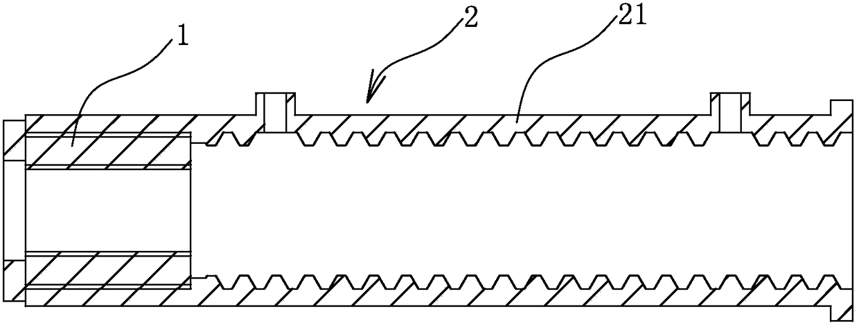
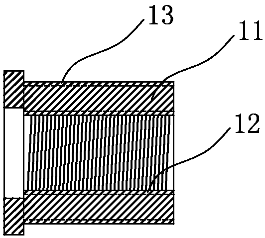
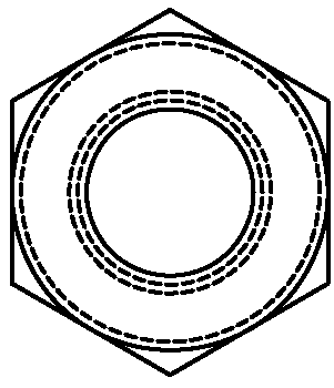
[0037] Such as figure 1 As shown, the semi-grouting sleeve assembly for the connection of the prefabricated horizontal longitudinal reinforcement of the cast-in-place beam-column joint of the prefabricated building includes a half-grouting sleeve 2 and an integrated nut and bolt 1 for connecting with the half-grouting sleeve; the half-grouting sleeve The grouting sleeve 2 includes a straight metal cylinder 21. One end of the cylinder 21 is a threaded end 22 provided with an internal thread, and the other end is a grouting end 23. The outer end face of the grouting end 23 is open for inserting the right prefabricated Composite beam horizontal longitudinal reinforcement 4; the one-piece nut and bolt 1 includes a body 11 and an internal thread 12 and an external thread 13 provided on the body, and the internal thread 12 is used to connect with the...


PUM


Abstract

The invention discloses a semi-grouting sleeve assembly of a precast beam steel connection of cast-in-place beam column joints and an application thereof. The semi-grouting sleeve assembly comprises asemi-grouting sleeve and an integral nut bolt, wherein the integral nut bolt is connected with the semi-grouting sleeve. The semi-grouting sleeve comprises a straight cylindrical body, one end of thestraight cylindrical body is a threaded end provided with an internal thread, the other end is a grouting end, and the outer end opening of the grouting end is used to insert a horizontally longitudinal rebar of a prefabricated laminated beam. The integral nut bolt includes a body and internal and external threads disposed on the body. The internal threads are used to connect a thread with one end of the horizontally longitudinal rebar of another prefabricated beam. The semi-grouting sleeve assembly replaces an existing full-grouting sleeve with a precast beam steel connection, the length andweight are reduced by nearly half, and the sleeve price is reduced. When the beam steel used for cast-in-place beam column joints are connected, the requirements on the length of a column section arealso correspondingly reduced, thereby avoiding the increase of the length dimension of the column section and the cost is low.

Description

technical field [0001] The invention relates to the field of prefabricated beam reinforcement connection of cast-in-place joints of prefabricated buildings, in particular to a prefabricated beam used for cast-in-place beam-column joints of prefabricated buildings at the mid-column node, connecting two horizontal longitudinal steel bars of relative prefabricated composite beams Grout sleeve assembly and its application. Background technique [0002] The development of prefabricated buildings is a major change in the way of construction, which is conducive to saving resources and energy, reducing construction pollution, improving labor production efficiency and quality and safety levels, and is conducive to promoting the deep integration of the construction industry and information industrialization, cultivating new industries and new drivers, and promoting Eliminate excess capacity. At present, it is necessary to accelerate the establishment of a standard system for the desi...

Claims


Application Information

Patent Timeline
IPC IPC(8): E04C5/16E04B1/21
CPCE04B1/21E04C5/165
Inventor 曾宪纯马旭新李海波王立曾庆路张玉强
Owner 浙江省建筑科学设计研究院建筑设计所
Why Eureka
Try Eureka