
Device for controlling distribution of drive force in a four-wheel drive vehicle

a four-wheel drive, drive technology, applied in vehicle position/course/altitude control, process and machine control, instruments, etc., can solve the problems of inferior four-wheel drive performance of achieve the same four-wheel drive performance in electric motor operating mode and electric motor non-operating mode. , to achieve the effect of greater precision and greater respons

Active Publication Date: 2015-10-22
NISSAN MOTOR CO LTD
View PDF21 Cites 6 Cited by
  • Summary
  • Abstract
  • Description
  • Claims
  • Application Information

AI Technical Summary

Benefits of technology

The present invention provides a device for controlling the distribution of drive force in a four-wheel drive vehicle that can achieve the same four-wheel drive performance in both the electric motor operating mode and the electric motor non-operating mode, by upwardly correcting the command value for the distribution of drive force in the electric motor operating mode to compensate for the lower estimation precision of the electric motor output torque. This ensures that the same four-wheel drive performance can be achieved in both modes, even if the conditions are the same.

Problems solved by technology

When the above-described drive force distribution control device for a common four-wheel drive vehicle is used to control the drive force distribution of a hybrid four-wheel drive vehicle, problems such as the following have been confirmed to occur.
Therefore, in the electric motor operating mode and the electric motor non-operating mode of a hybrid four-wheel drive vehicle, the resulting four-wheel drive performance differs even under the same conditions, creating a disparity between the two modes and causing a problem in that there is a sense that the four-wheel drive performance of the electric motor operating mode is inferior to that of the electric motor non-operating mode.
Therefore, the disparity in four-wheel drive performance between the two modes described above causes a drawback in that the same four-wheel drive performance cannot be achieved in both the electric motor operating mode and the electric motor non-operating mode.

Method used


Image

  • Device for controlling distribution of drive force in a four-wheel drive vehicle
  • Device for controlling distribution of drive force in a four-wheel drive vehicle
  • Device for controlling distribution of drive force in a four-wheel drive vehicle

Examples


embodiment 1

[0032]Configuration

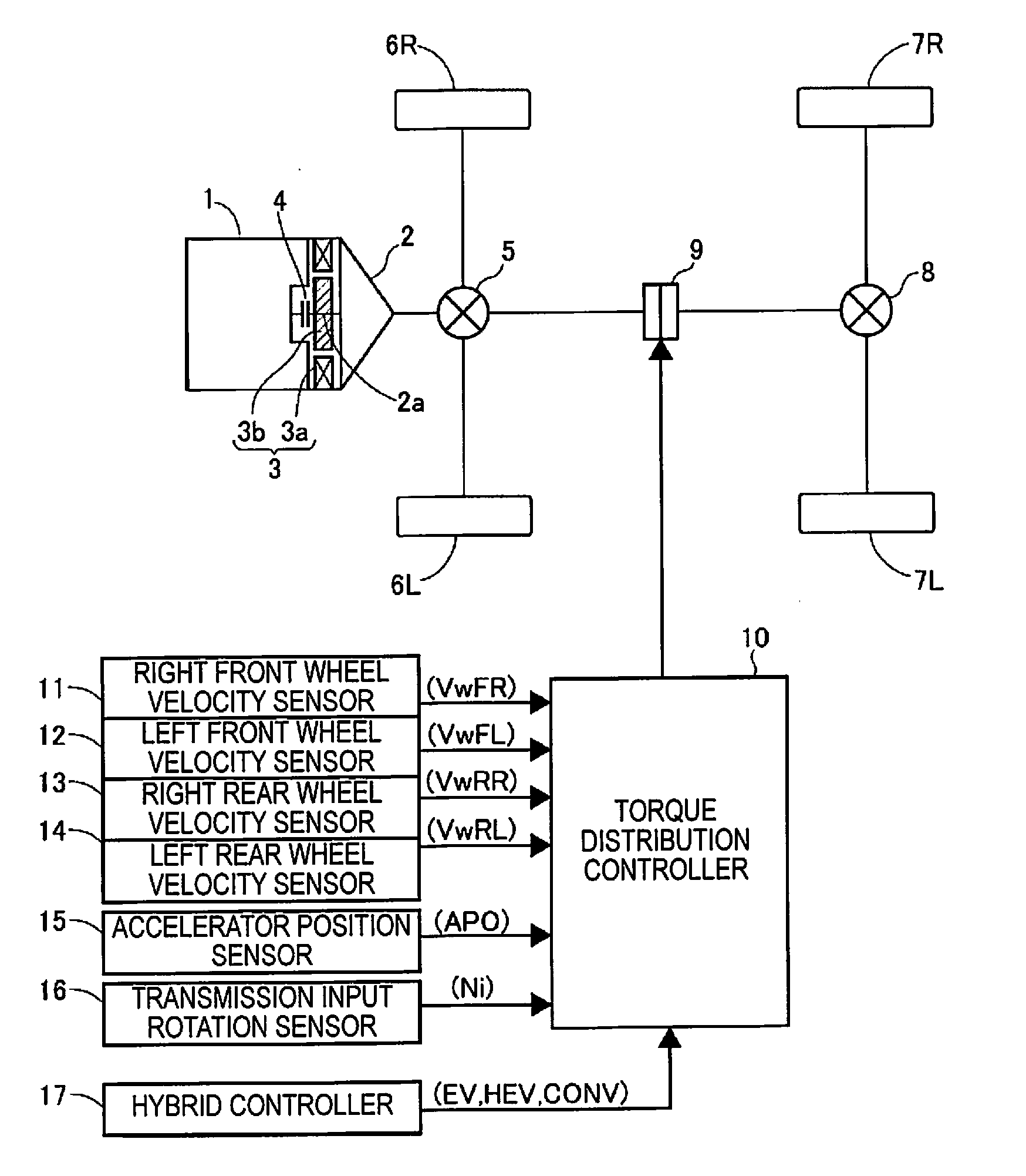
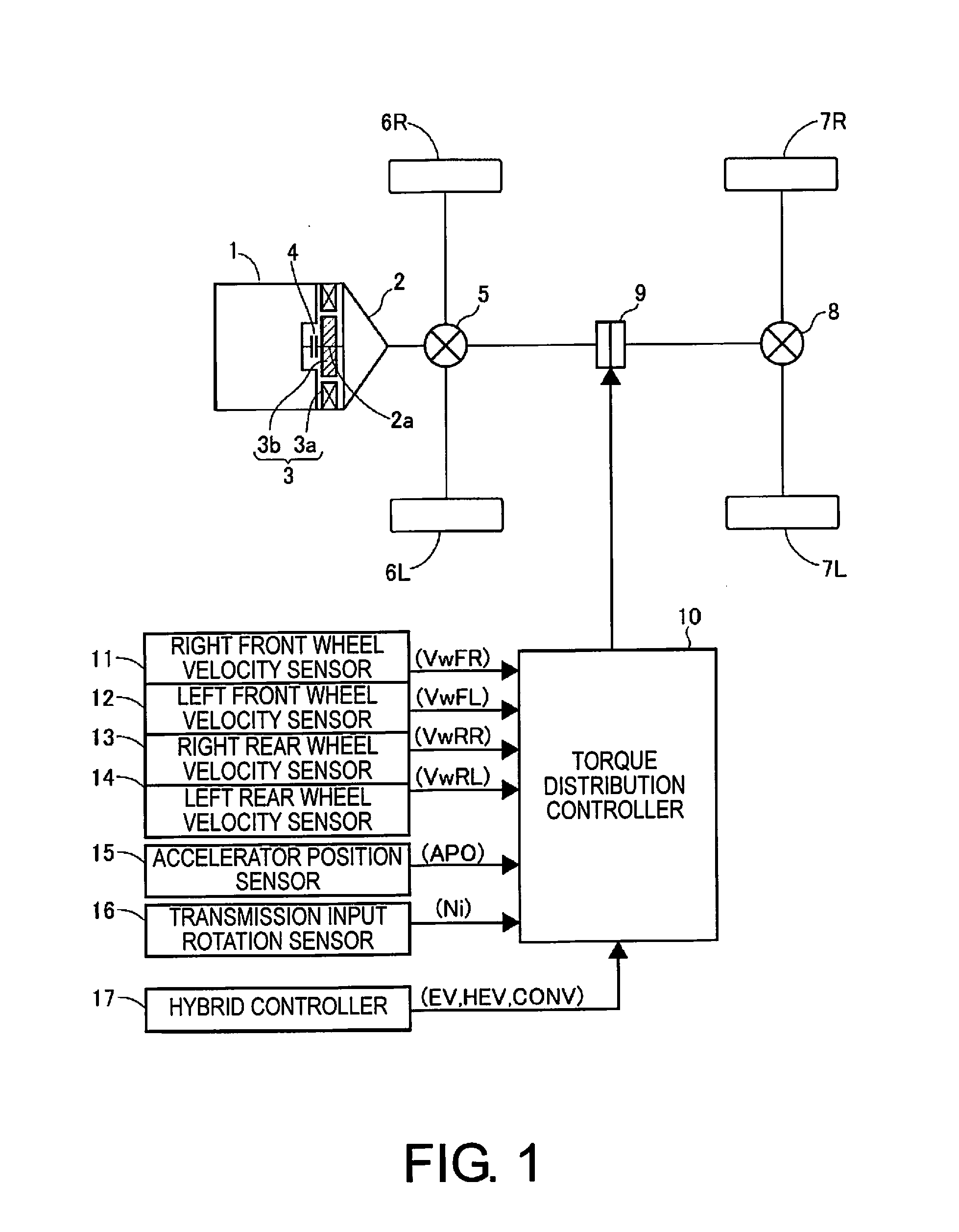
[0033]FIG. 1 is a schematic plan view of a power train of a hybrid four-wheel drive vehicle comprising a drive force distribution control device as an embodiment of the present invention, as seen from above the vehicle, where the symbol 1 denotes an engine as one motive power source, 2 denotes an automatic transmission, and an electric motor 3 as another motive power source is interposed between the engine 1 and the automatic transmission 2.

[0034]The electric motor 3 is formed from an annular stator 3a disposed in a fixed manner inside a motor housing, and a rotor 3b disposed concentrically inside the annular stator 3a with a radial gap in between, the rotor 3b being joined to a transmission input shaft 2a.

[0035]The transmission input shaft 2a is linked in a detachable manner to the engine 1 by a clutch 4.

[0036]An output shaft of the automatic transmission 2 is linked to left and right front wheels (main drive wheels) 6L, 6R via a front differential gear device 5...


PUM


Abstract

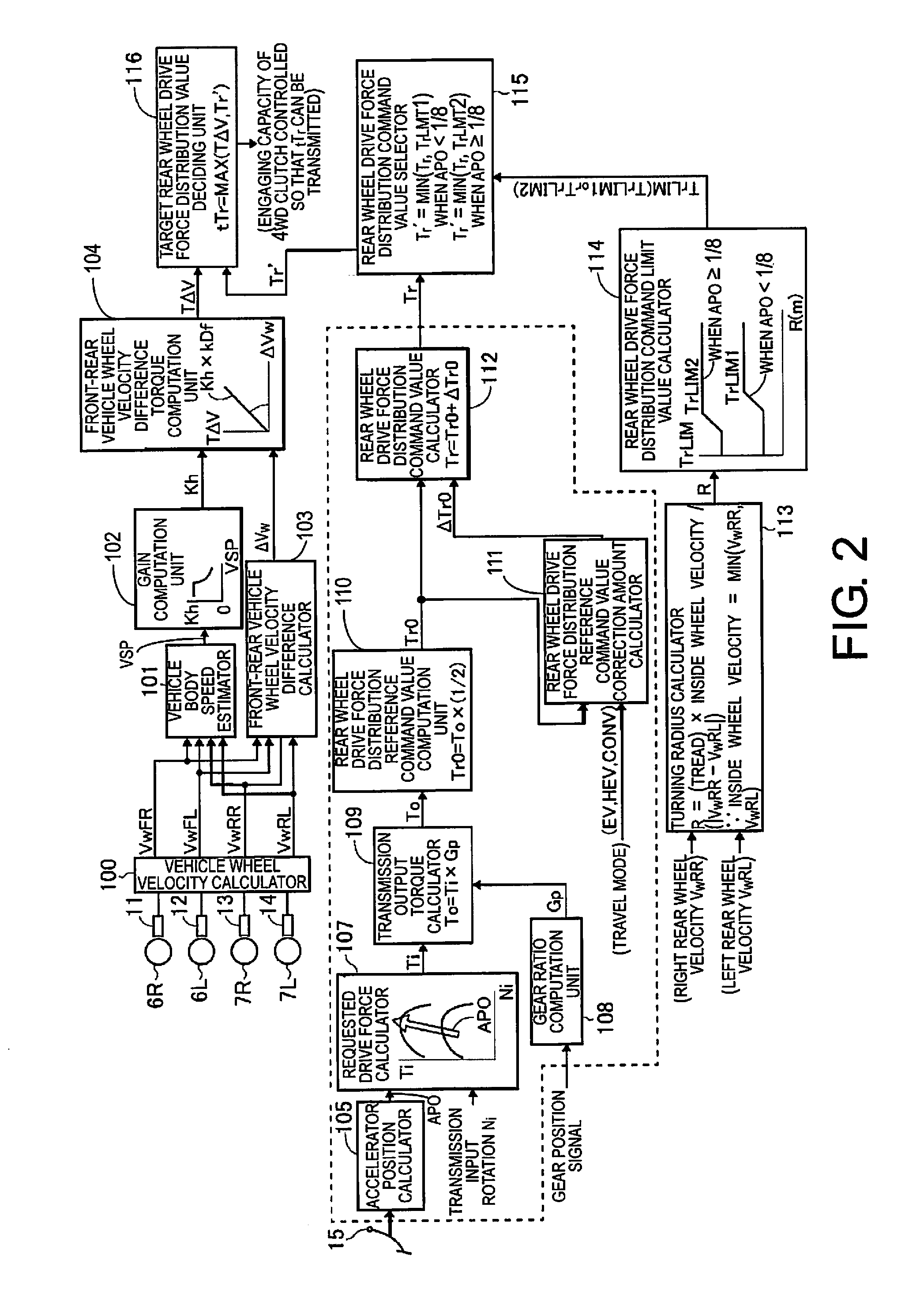
A device for controlling the distribution of drive force includes a driven wheel drive force distribution reference command value calculator configured to determine a driven-wheel-oriented drive force distribution reference command value from the estimated value of the drive force sent to the drive wheels and a drive force reference distribution ratio, and a driven wheel drive force distribution command value calculator configured to determine a driven-wheel-oriented drive force distribution command value by correcting the driven wheel drive force distribution reference command value by a correction amount that differs between the electric motor operating mode and the electric motor non-operating mode, and to make the correction amount for the electric motor operating mode greater than the correction amount for the electric motor non-operating mode.

Description

CROSS-REFERENCE TO RELATED APPLICATIONS[0001]This application is a U.S. National stage application of International Application No. PCT / JP2013 / 081305, filed Nov. 20, 2013, which claims priority to JP Patent Application No. 2012-270182 filed on Dec. 11, 2012, the contents of each of which are hereby incorporated herein by reference.BACKGROUND[0002]1. Field of the Invention[0003]The present invention relates to a device for controlling the distribution of drive force in a hybrid four-wheel drive vehicle, the device comprising an engine and an electric motor as motive power sources, and having an electric travel mode (EV mode) that relies only on the electric motor, an electric motor operating mode in the manner of a hybrid travel mode (HEV mode) that relies on the engine and the electric motor, and an electric motor non-operating mode which is like a conventional travel mode (CONV mode) that relies only on the engine.[0004]2. Background Information[0005]The device disclosed in Japanes...

Claims


Application Information

Patent Timeline
Patent Type & Authority Applications(United States)
IPC IPC(8): B60W10/119B60W10/02B60K6/52B60W20/00B60W10/08B60L50/16
CPCB60W10/119B60W20/10B60W10/08Y10S903/916B60W10/02B60W2720/403Y10S903/93B60K6/52B60K6/48B60K23/0808B60L15/2054B60L2240/423B60L2240/463B60L2260/28B60L2260/42B60W20/00B60W2050/0026B60W2510/1005B60W2520/10B60W2520/263B60W2540/10B60L50/16Y02T10/62Y02T10/64Y02T10/7072Y02T10/72B60W10/11B60W30/1882B60W2710/1022Y02T10/70
Inventor SUGITANI, OSAMUTAKASAKI, TOSHIHARUTANAKA, KOTARO
Owner NISSAN MOTOR CO LTD
Learn More