
Insulation insert with an integrated shielding element

a shielding element and insert technology, applied in the direction of securing/insulating coupling contact members, coupling device connections, electrical devices, etc., can solve the problems of time-consuming packaging of such plug-in connectors, and the possibility of errors in fastening the shielding braid via a crimp ring, so as to achieve convenient packaging and reliable shielding

Active Publication Date: 2015-10-15
HARTING ELECTRIC GMBH & CO KG
View PDF15 Cites 10 Cited by
  • Summary
  • Abstract
  • Description
  • Claims
  • Application Information

AI Technical Summary

Benefits of technology

The invention provides a plug-in connector that offers reliable shielding and easy packaging. The insulation insert and shielding element are formed as a single component, eliminating one component and one packaging step. The structural unity of the components ensures a more reliable transfer of cable shielding to the plug-in connector housing. The insulation insert can be clamped in the plug-in connector housing, making the packaging process easier. The insulation insert contains multiple contact elements for electrically contacting in each case one cable core of a multicore cable, and it is expedient to shield the contact elements from each other to improve signal integrity and reduce interferences. The overall design simplifies the packaging process and accelerates the overall manufacturing process.

Problems solved by technology

Due to the large number of parts, the packaging of such plug-in connectors is quite time-consuming.
Moreover, fastening the shielding braid via a crimp ring constitutes a potential source of errors because the crimp ring can easily slip whilst being inserted into the plug-in connector housing.

Method used


Image

  • Insulation insert with an integrated shielding element
  • Insulation insert with an integrated shielding element
  • Insulation insert with an integrated shielding element

Examples


Embodiment Construction

[0024]An embodiment example of the invention is shown in the drawings and will be explained in more detail below, wherein:

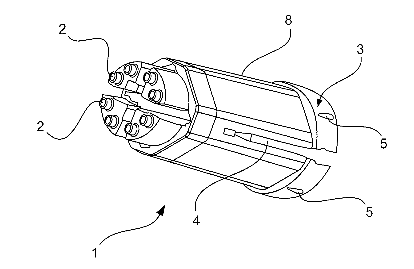
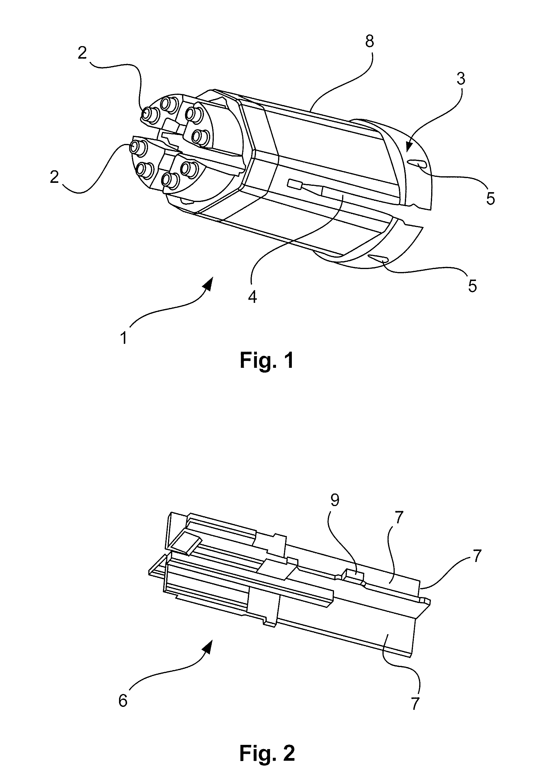
[0025]FIG. 1 shows a perspective view of an insulation insert of a plug-in connector,

[0026]FIG. 2 shows a perspective view of a second shielding element,

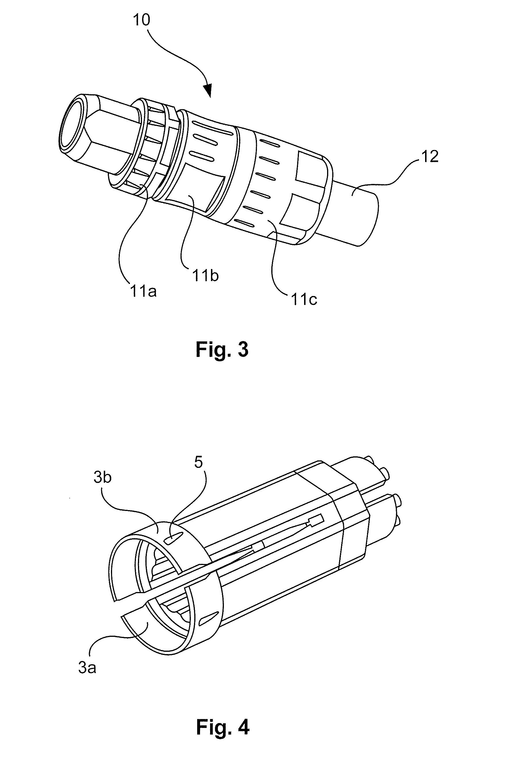
[0027]FIG. 3 shows a perspective view of a complete plug-in connector with a connected multicore cable, and

[0028]FIG. 4 shows a further perspective view of the insulation insert of the plug-in connector.

[0029]FIG. 1 shows a possible embodiment of an insulation insert 1 according to the invention. The insulation insert 1 substantially has the form of a hollow cylinder that is provided on the plug-in side with bores 2 in the end face, through each of which a contact element (not shown) protrudes. On the connection side, the insulation insert 1 has a shielding element 3 that is interrupted by axially extending slots 4. The axial slots 4 extend beyond the shielding area further in the plug-in direction. The length of...


PUM


Abstract

The invention relates to an insulation insert that can be inserted into a plug-in connector housing (11) of a plug-in connector (10), wherein in the insulation insert (1), at least one contacting element for electrically contacting a conductor core of a cable (12) to be connected may be provided, wherein the insulation insert (1) is provided in one area with a conductive coating, wherein the coated area forms a shielding element (3) that can be electrically contacted with a shielding braid of the cable (12) to be connected and at the same time with the plug-in connector housing (11), and wherein the insulation insert (1) and the shielding element (3) are integrally formed in.

Description

[0001]The invention relates to an insulation insert of a plug-in connector according to the preamble of claim 1 and to a plug-in connector that uses such an insulation insert according to claim 9.[0002]Plug-in connectors with such insulation inserts shield the contact elements against electromagnetic radiation and in this way ensure good signal integrity. They are particularly suitable for high data transmission rates.PRIOR ART[0003]EP 945929 B1 shows a plug-in connector, the contact elements of which are inserted into shielded chambers of the insulation insert. The shielding braid of the connected cable is fastened to the insulation insert by means of a crimp ring.[0004]It is also known from the prior art to crimp the shielding braid of the connected cable between a seal and a shielding element that is fastened to the insulation insert.[0005]Due to the large number of parts, the packaging of such plug-in connectors is quite time-consuming. Moreover, fastening the shielding braid vi...

Claims


Application Information

Patent Timeline
Patent Type & Authority Applications(United States)
IPC IPC(8): H01R13/6599H01R13/40H01R13/6592
CPCH01R13/6599H01R13/40H01R13/6592H01R13/6585
Inventor POST, DIRK PETERGENAU, MELANIEKRAEMER, KLAUSBEUTH, VOLKERSCHREIER, STEPHAN
Owner HARTING ELECTRIC GMBH & CO KG
Learn More