Plasma ignition device for internal combustion engines

a technology of internal combustion engine and ignition device, which is applied in the direction of electric ignition installation, machines/engines, mechanical equipment, etc., can solve the problems of not providing technical means capable of intervening on timing, the disclosure does not provide technical means, and the known state of the art has drawbacks, etc., to reduce the fatigue of electric energy sources, and minimize electric energy loss

Inactive Publication Date: 2015-10-15
ELDOR CORP SPA
View PDF2 Cites 7 Cited by
  • Summary
  • Abstract
  • Description
  • Claims
  • Application Information

AI Technical Summary

Benefits of technology

[0042]A further aim of the present disclosure is to disclose a plasma ignition device, as specified, which is capable of minimizing electric energy loss in all stages of operation and particularly in the stage for electromagnetic charging of the primary winding of the ignition coil.
[0043]A consequent aim of the present disclosure is to provide a d

Problems solved by technology

The diode can be controlled only in the ignition stage, but it cannot be controlled when it is switching off.
Therefore, said disclosure does not provide technical means capable of intervening on the timing specific to the described cycle, keeping it constant even with variations in the engine speed, in that the closure of the SCR diode will always take place at the moment when energy in the capacitor is being discharged.
However, some drawbacks exist in the known state of the art.
One drawback of the known state of the art is the considerable complexity of the control and driving circuits of the considered devices, which require a relatively large number of components for proper functioning, which leads to problems concerning reliability and costs.
Another drawback of the prior art consists in the impossibility of reducing the overall dimensions of the considered device, whereby it cannot in fact be incorporated in other components.
A further drawback consists in the possibility of significant energy loss in the electromagnetic charging stage due to the presence of a number of series inductors at the primary control circuit, which leads to a greater demand for electric energy at the

Method used


Image

  • Plasma ignition device for internal combustion engines
  • Plasma ignition device for internal combustion engines
  • Plasma ignition device for internal combustion engines

Examples


Embodiment Construction

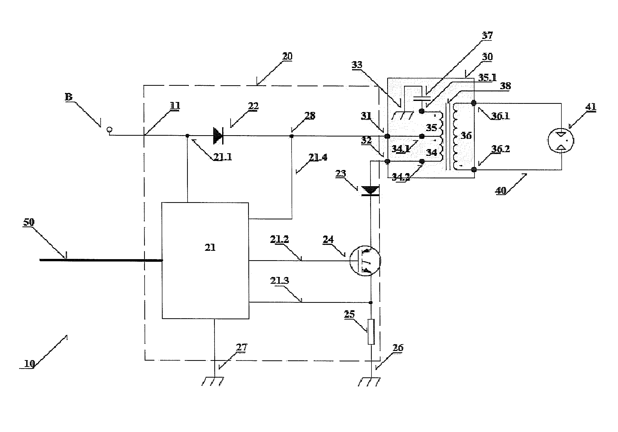
[0054]In FIG. 1, the plasma ignition device for internal combustion engines, the object of the present disclosure, is indicated in its entirety by the number 10. It principally comprises:

[0055]a driving and analog and / or digital control unit 20;

[0056]an ignition coil 30;

[0057]a spark plug 40;

[0058]a voltage generator, for example a battery B;

[0059]connections 50 from and for an engine control unit, ECU (in and of itself known in the art and not illustrated herein).

[0060]Said driving and analog and / or digital control unit 20 substantially comprises:

[0061]a driving and control unit 21;

[0062]a first diode 22;

[0063]a second diode 23;

[0064]a static switch 24;

[0065]a resistor 25;

[0066]a voltage control device 28.

[0067]Said ignition coil 30 substantially comprises:

[0068]a first primary winding 34;

[0069]a second primary winding 35;

[0070]a secondary winding 36;

[0071]a capacitor 37;

[0072]an electromagnetic core 38.

[0073]Said spark plug 40 comprises:

[0074]a discharge “gap”41.

Main Electrical Co...


PUM


Abstract

A plasma ignition device for internal combustion engines is described. It comprises a driving and analog and/or digital control unit, an ignition coil and a spark plug, interconnected each other in a circuit by means of electrical/electronic connection means. The ignition coil comprises two primary windings connected in series each other, having a central electrical connection between the first primary winding and the second primary winding, for electrically charging a capacitor, connected in series to the two primary windings, and for magnetically charging a magnetic core magnetically coupled to a secondary winding of the ignition coil, in order to generate a potential difference across a discharge “gap” of a spark plug.

Description

BACKGROUND[0001]1. Technical Field[0002]The present disclosure concerns a plasma ignition device for internal combustion engines.[0003]2. Description of the Related Art[0004]There are known internal combustion engines in the prior art that operate by compression of a mixture of air and fuel and the resulting generation of a spark, which, by igniting said mixture, generates a controlled explosion inside one or more combustion chambers within the engine for the purpose of supplying power to said internal combustion engine. The spark is typically generated and supplies high voltage energy to a spark plug exhibiting a specific distance between the electrodes, which is called the “discharge gap”. The resulting discharge triggers combustion of the mixture.[0005]The efficiency and the pollutant emissions characteristic of an internal combustion engine are partly determined by the quality and modes of combustion of the mixture.[0006]In the case in which combustion is not complete, or the sp...

Claims


Application Information

Patent Timeline
IPC IPC(8): F02P23/04F02P3/04
CPCF02P3/0407F02P23/04F02P9/007F02P15/10F02D2400/18F02P17/12F02P3/02F02P3/06
Inventor FORTE, PASQUALEBONFANTI, LUCA FRANCOCOLOMBOTTO, AMEDEO
Owner ELDOR CORP SPA
Why Eureka
Try Eureka