Fuel injection apparatus for internal combustion engine

a fuel injection apparatus and internal combustion engine technology, applied in the direction of machines/engines, electrical control, instruments, etc., can solve the problems of inability to perform noise removal by the signal replacement process, and the inability to detect the pressure drop of the in-cylinder

Active Publication Date: 2015-10-15
HONDA MOTOR CO LTD +1
View PDF3 Cites 0 Cited by
  • Summary
  • Abstract
  • Description
  • Claims
  • Application Information

AI Technical Summary

Benefits of technology

The patent is about a configuration that reduces fuel injection noise in an engine. It achieves this by reducing the grounding impedance of the output terminal connected to the actuating solenoid of the other fuel injection valve when it is actuated. This prevents fuel injection noise from entering the detection signal of the in-cylinder pressure sensor mounted on the other fuel injection valve. The configuration also limits the current from the input terminal to the output terminal connected to the actuating solenoid of the other fuel injection valve. This prevents excessive current and ensures the fuel injection noise does not enter the detection signal of the in-cylinder pressure sensor. Overall, this configuration improves engine performance and reduces noise levels.

Problems solved by technology

Accordingly, there exists a problem that the detection accuracy of the in-cylinder pressure falls in the period during which the fuel injection noise enters the detection signal.
Further, if entering of the fuel injection noise occurs in the expansion stroke, it is impossible to perform the noise removal by the signal replacing process.

Method used


Image

  • Fuel injection apparatus for internal combustion engine
  • Fuel injection apparatus for internal combustion engine
  • Fuel injection apparatus for internal combustion engine

Examples


Embodiment Construction

[0023]Preferred embodiments of the present invention will now be described with reference to the drawings.

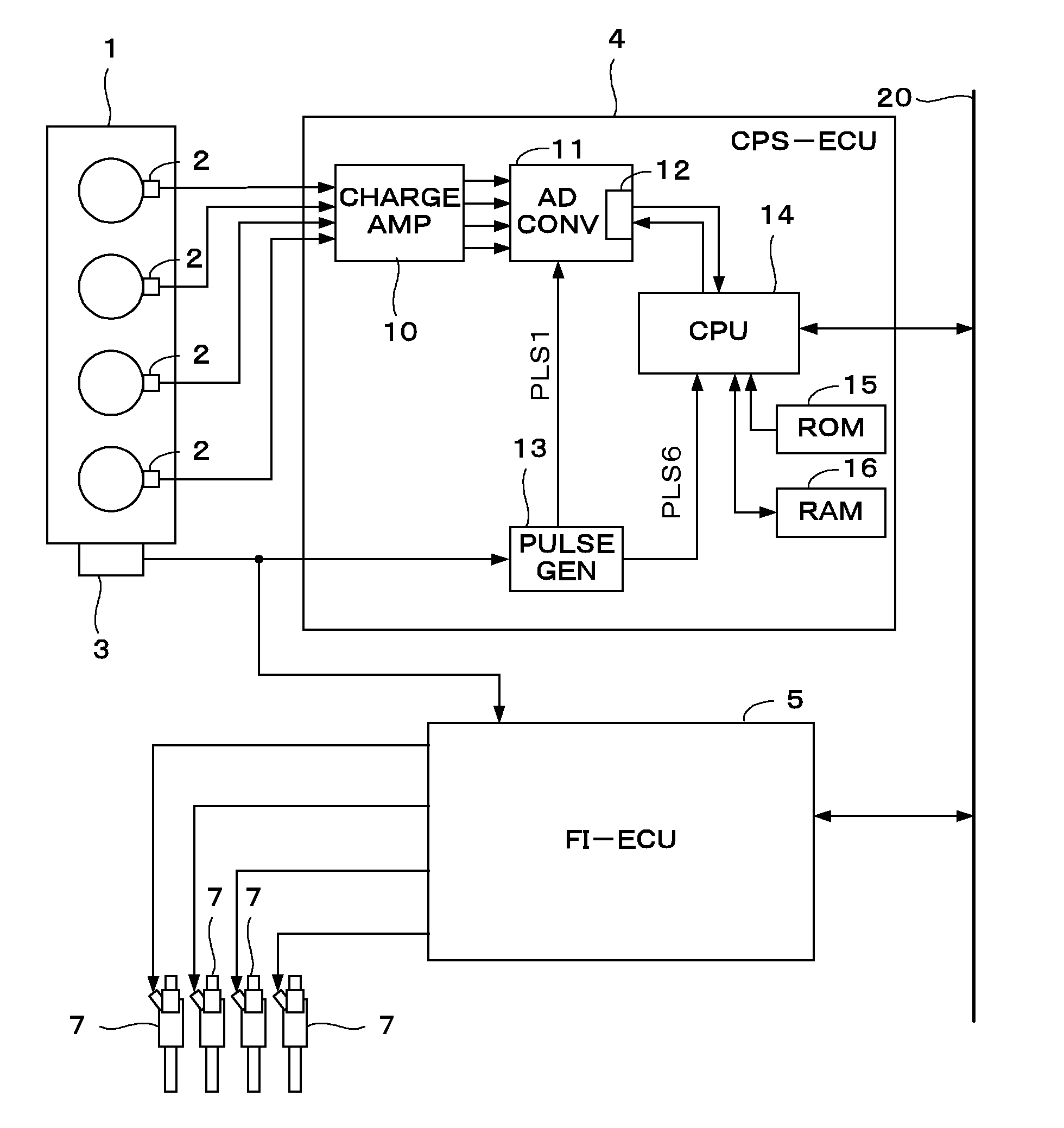
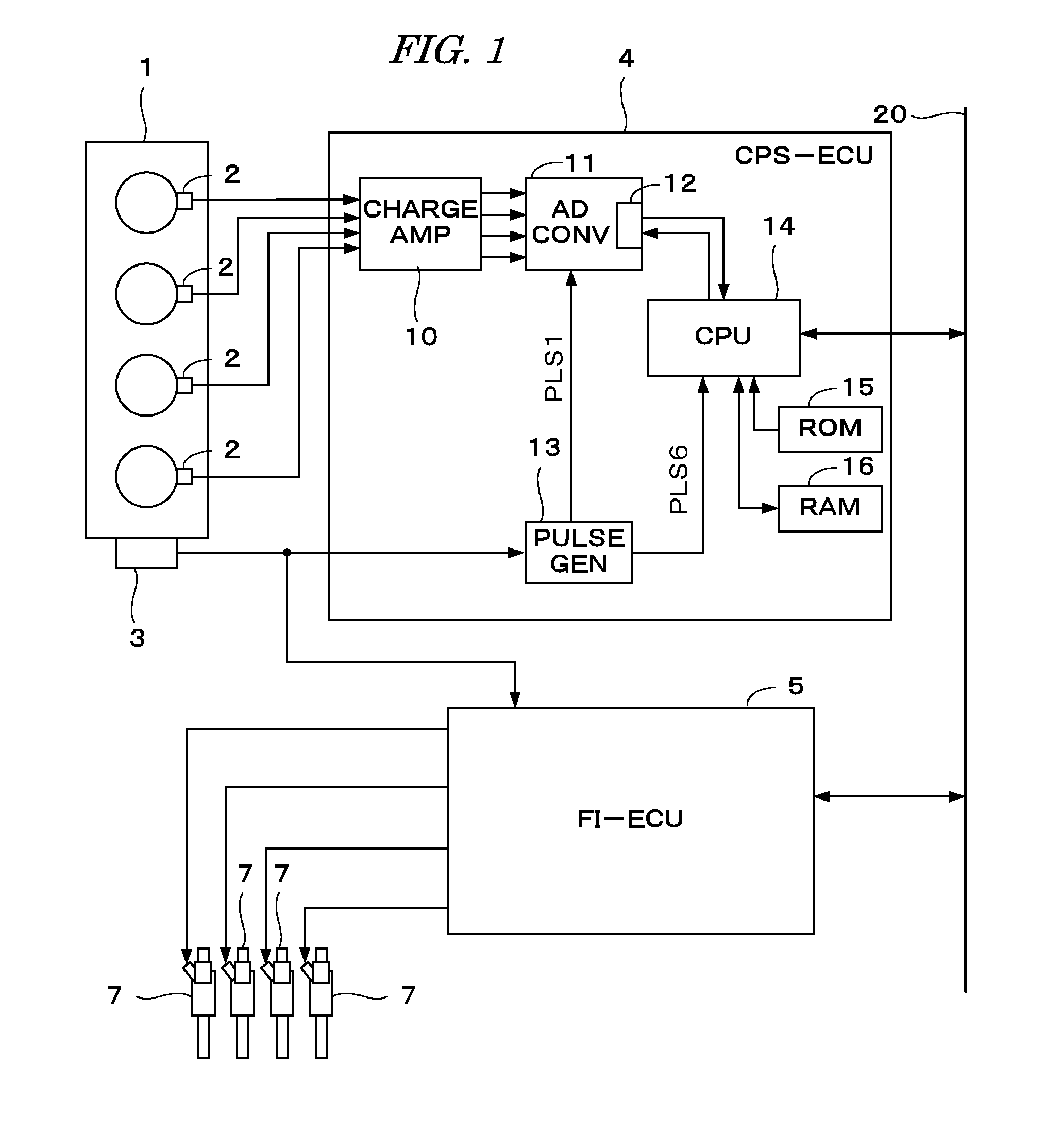
[0024]FIG. 1 shows a configuration of a control apparatus for an internal combustion engine according to one embodiment of the present invention. Each cylinder of a 4-cylinder direct injection internal combustion engine (hereinafter referred to as “engine”) 1 is provided with an in-cylinder pressure sensor 2 for detecting an in-cylinder pressure PCYL. In this embodiment, the in-cylinder pressure sensor 2 is integrated with a fuel injection valve 7 mounted on each cylinder as shown in FIG. 2. It is to be noted that the in-cylinder pressure sensor 2 and the fuel injection valve 7 are separately shown in FIG. 1, since FIG. 1 is a drawing for explaining the configuration of the control apparatus.

[0025]The in-cylinder pressure sensor 2 consists of a piezo-electric element having a ring-like shape, and is disposed at a position so that the piezo-electric element surrounds an injection...


PUM


Abstract

A fuel injection apparatus for an internal combustion engine having a plurality of cylinders is provided. The fuel injection apparatus includes a fuel injection valve and an in-cylinder pressure sensor disposed for each of the plurality of cylinders. The fuel injection valve injects fuel into a combustion chamber of each cylinder and the in-cylinder pressure sensor detects a pressure in the combustion chamber. The fuel injection apparatus includes a cylinder pair actuating circuit and a noise suppressing circuit. The cylinder pair actuating circuit is provided corresponding to a cylinder pair which is a combination of two cylinders included in the plurality of cylinders, for supplying actuating current to two actuating solenoids of the two fuel injection valves mounted on the cylinder pair. The noise suppressing circuit is provided between the cylinder pair actuating circuit and the actuating solenoids. The noise suppressing circuit includes two output terminals connected respectively to the two actuating solenoids of the two fuel injection valves. When actuating one of the two injection valves, the grounding impedance between the output terminal connected to the actuating solenoid of the other of the two injection valves and the ground, is reduced.

Description

BACKGROUND OF THE INVENTION[0001]1. Field of the Invention[0002]The present invention relates to a fuel injection apparatus having a fuel injection valve for injecting fuel into a combustion chamber of an internal combustion engine, and particularly to the fuel injection apparatus provided with an in-cylinder pressure sensor which is mounted on a tip portion of the fuel injection valve and detects a pressure in the combustion chamber.[0003]2. Description of the Related Art[0004]Japanese Patent Laid-open Publication No. 2014-1700 discloses a control apparatus for an internal combustion engine having a fuel injection valve for injecting fuel into a combustion chamber of the engine, and an in-cylinder pressure sensor which is mounted on a tip portion of the fuel injection valve and detects a pressure in the combustion chamber. According to this apparatus, reduction in accuracy of the control based on the output signal of the in-cylinder pressure sensor is prevented by reducing a fuel i...

Claims


Application Information

Patent Timeline
IPC IPC(8): F02M57/00F02M51/00F02M51/06F02D41/38F02D41/04
CPCF02M57/005F02D41/38F02D2041/389F02M51/061F02M51/005F02D41/04F02D35/023F02D41/20F02D2041/1432F02D2041/2048F02D2041/2058G01L23/10
Inventor AKAZAKI, SHUSUKESAITO, SHUNICHIAKIYAMA, KAORU
Owner HONDA MOTOR CO LTD
Why Eureka
Try Eureka