
Burner arrangement, combustor, gas turbine engine and method for determining a rate of soot deposition in gas turbine combustors

a gas turbine engine and combustor technology, applied in the direction of turbine/propulsion engine ignition, combustion types, burner control devices, etc., can solve the problem of difficult measurement, and achieve the effect of accelerating the accumulation of deposition and increasing the amount of deposits

Inactive Publication Date: 2015-10-15
SIEMENS AG
View PDF3 Cites 10 Cited by
  • Summary
  • Abstract
  • Description
  • Claims
  • Application Information

AI Technical Summary

Benefits of technology

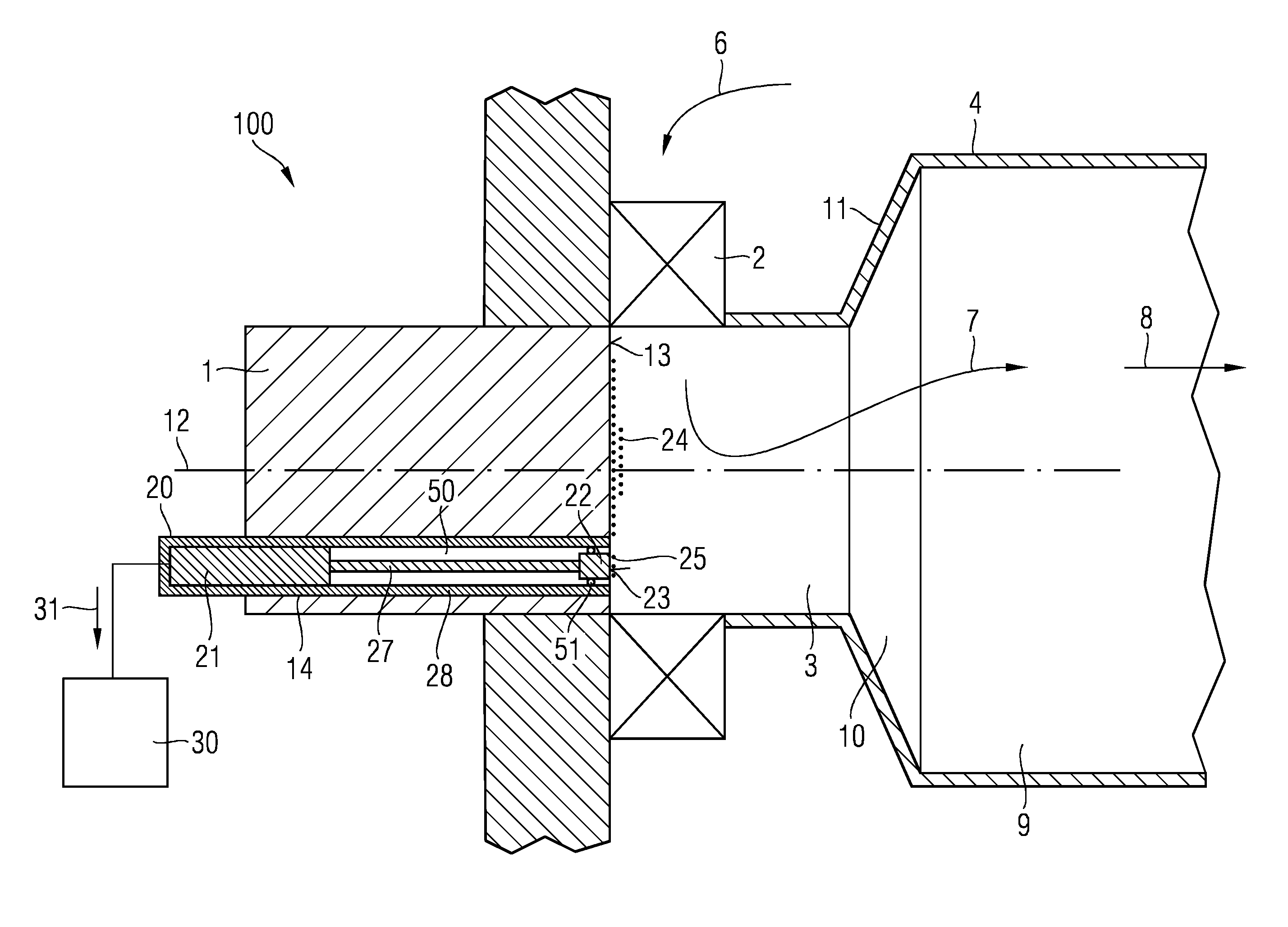
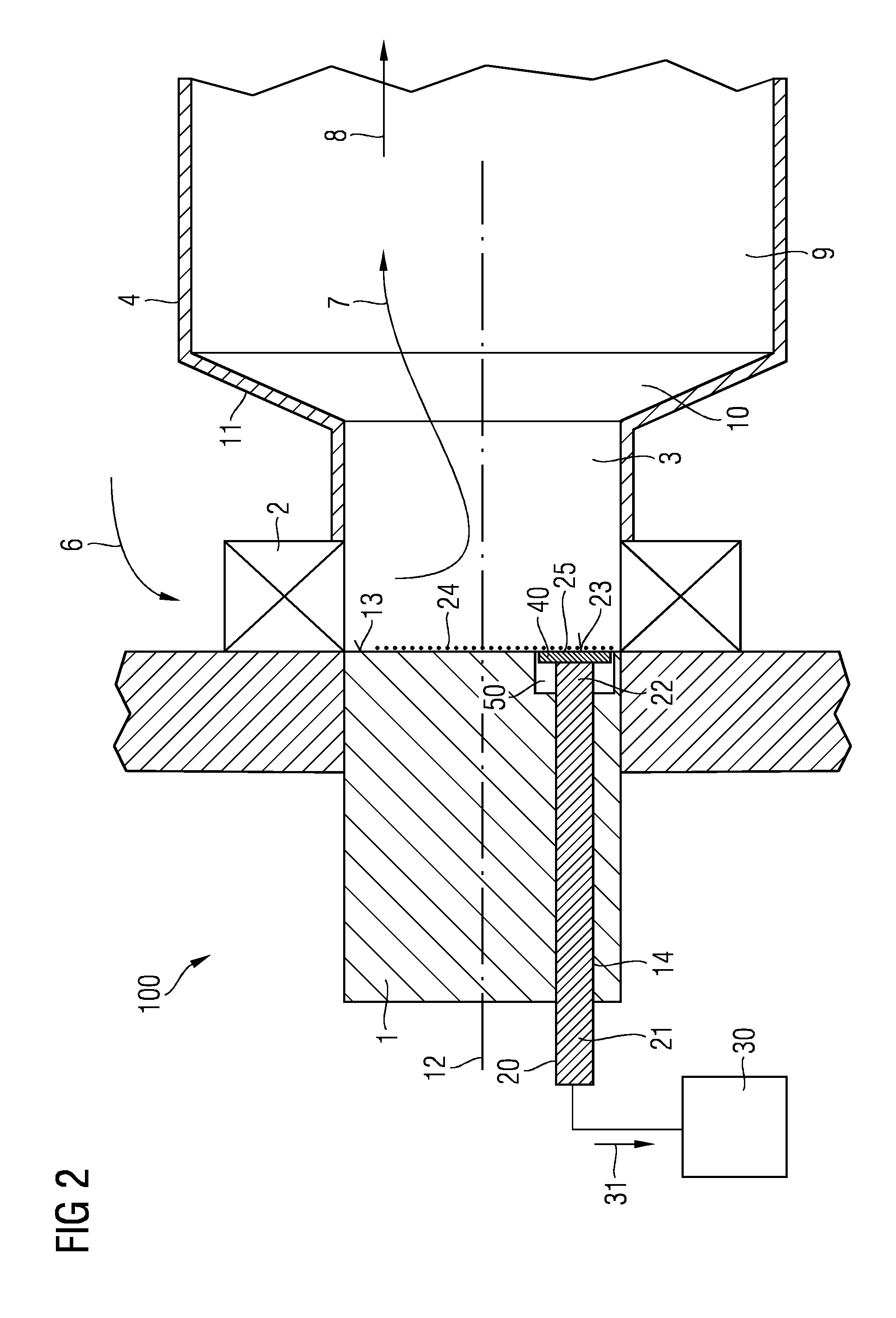
The patent describes a burner arrangement for a gas turbine engine that reduces the need for manual labor to evaluate deposition. It allows for measuring deposition in the combustor, which has high temperatures and pressures. The arrangement keeps all parts in place even at full power, and may withstand high temperatures using optics. The arrangement includes a diaphragm that collects combustion residues, providing an enhanced amount of deposits compared to the burner face, which correlates to the deposition on the burner face. This measurement is done indirectly with a component that allows for faster build-up of depositions.

Problems solved by technology

In this location measurements are difficult to be taken due to the pressure and temperatures involved within the combustor, for example 15 bar and circa 300° C. for or similar conditions.

Method used


Image

  • Burner arrangement, combustor, gas turbine engine and method for determining a rate of soot deposition in gas turbine combustors
  • Burner arrangement, combustor, gas turbine engine and method for determining a rate of soot deposition in gas turbine combustors
  • Burner arrangement, combustor, gas turbine engine and method for determining a rate of soot deposition in gas turbine combustors

Examples


Embodiment Construction

[0043]Not shown in the figures, a gas turbine engine comprises a compressor section, a combustor section and a turbine section which are arranged adjacent to each other. In operation of the gas turbine engine air is compressed by the compressor section and the compressed air is provided to the combustor section with one or more combustors. Previously and in the following merely a single combustor is shown and discussed to show the inventive idea.

[0044]FIG. 1 shows a longitudinal section through a combustor, specifically a combustor within a gas turbine engine (the latter is not shown). The combustor comprises relative to a flow direction: a burner comprising a burner-head and a swirler 2 attached to the burner-head, a transition piece referred to as combustion pre-chamber 3, and a main combustion chamber 4. The burner-head comprises a burner body 1 or may be the same as the burner body 1. The main combustion chamber 4 has for example a diameter being larger than the diameter of the ...


PUM


Abstract

A burner arrangement for a combustor of a gas turbine engine including a burner body is provided. The burner arrangement includes a cut-out and a burner face, the cut-out piercing the burner face, a sensor device installed in the cut-out and a first part fixed to the burner body and a second part having a tip surface, the sensor device being configured such that the second part is able to move relative to the burner face, and further including a data evaluation unit. The sensor device generates information signals corresponding to a magnitude and / or a period of the oscillation of the second part relative to the first part, the data evaluation unit collects the received information signals and determines a grade of deposition of combustion residues on the burner face by evaluating the collected information signals.

Description

CROSS REFERENCE TO RELATED APPLICATIONS[0001]This application is the US National Stage of International Application No. PCT / EP2012 / 074419 filed Dec. 5, 2012, and claims the benefit thereof. The International Application claims the benefit of European Application No. EP 12161318 filed Mar. 26, 2012. All of the applications are incorporated by reference herein in their entirety.FIELD OF INVENTION[0002]The present invention relates generally to a burner arrangement for a combustor of a gas turbine engine, particularly for determining whether residues or soot are deposited.BACKGROUND OF INVENTION[0003]For gas turbine engines, there is a main target to provide low emission combustion systems. These systems may burn both natural gas and liquid fuel, e.g. gas oil, diesel, kerosene or heating oil. There may be problems with liquid fuel at low power in that combustion may be inefficient and there may be a built-up of soot in the combustor, particularly the combustor head.[0004]At low power c...

Claims


Application Information

Patent Timeline
IPC IPC(8): F02C7/00F23N5/24F23R3/28
CPCF02C7/00F23N2029/00F23N5/242F23R3/28F23D2900/00016F23N5/00F23R3/14F23R3/286F23D2208/10F23N2900/05005F23R2900/00004F23N2241/20F23N2229/00
Inventor PEARCE, ROBERT
Owner SIEMENS AG
Learn More