Control device for electric rotary machine

a control device and electric rotary machine technology, applied in electric devices, battery/fuel cell control arrangements, instruments, etc., can solve the problems of significant deviation from the optimal value, correction torque obtained, and difficulty in observing the actual rotation speed of the electric rotary machine to follow the target rotation speed, so as to suppress an excessive correction of the instruction torque, reduce the correction torque, and prevent the actual rotation speed of the electric rotary machine

Active Publication Date: 2015-10-15
DENSO CORP
View PDF8 Cites 12 Cited by
  • Summary
  • Abstract
  • Description
  • Claims
  • Application Information

AI Technical Summary

Benefits of technology

[0010]In a case in which the target rotation speed of the electric rotary machine is changed to decrease a difference between the target rotation speed and the actual rotation speed of the electric rotary machine, there is a possible case in which the correction torque calculated by the correction torque calculation means becomes an insufficient torque in order to follow the target rotation speed of the electric rotary machine. In order to solve this, the control device for the electric rotary machine having the structure previously described is equipped with the correction rate correction me...

Problems solved by technology

When the instruction torque is limited in the control device performing the rotation speed control on the basis of the target rotation speed, it becomes difficult for the actual rotation speed of the electric rotary machine to follow the target rotation speed.
After this, when the target rotation speed is adjusted to decrease the difference between the target rotation speed ...

Method used


Image

  • Control device for electric rotary machine
  • Control device for electric rotary machine
  • Control device for electric rotary machine

Examples


first exemplary embodiment

[0020]A description will be given of the control device for an electric rotary machine according to a first exemplary embodiment. The concept of the control device according to the present invention is applied to a motor vehicle equipped with main engines such as an electric rotary machine and an internal combustion engine.

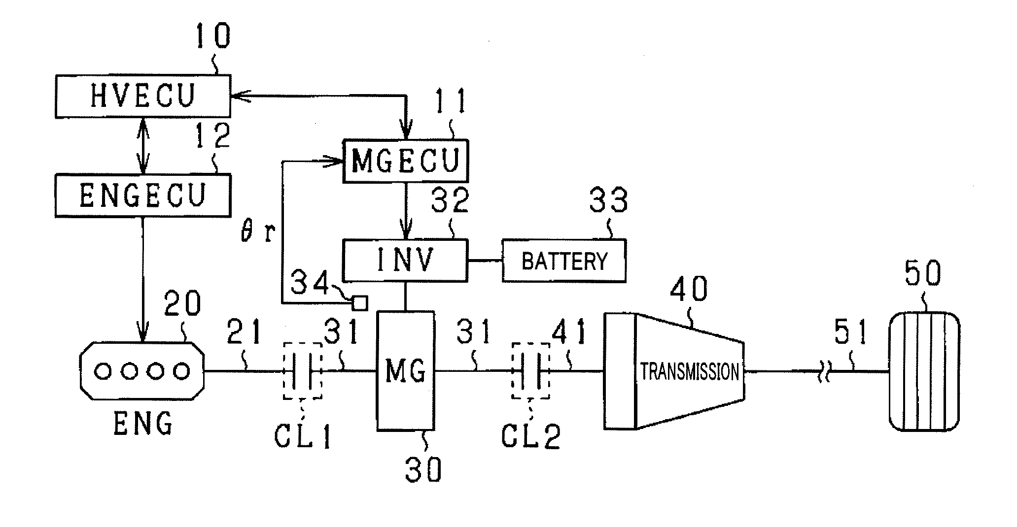
[0021]As shown in FIG. 1, a motor vehicle is equipped with a HVECU (hybrid vehicle ECU) 10, a MGECU (motor generator ECU) 11, an ENGECU (engine ECU) 12, an internal combustion engine 20, a motor generator 30 as an electric rotary machine, a transmission 40, and wheels 50.

[0022]The motor vehicle uses the internal combustion engine 20 and the motor generator 30 as a drive power source. A first clutch CL1 is connected to a rotary shaft 31 of the motor generator 30 at the internal combustion engine 20 side. The first clutch CL1 provides an engagement state and a disengagement state. That is, in the engagement state of the first clutch CL1, the rotary shaft 31 of the m...

second exemplary embodiment

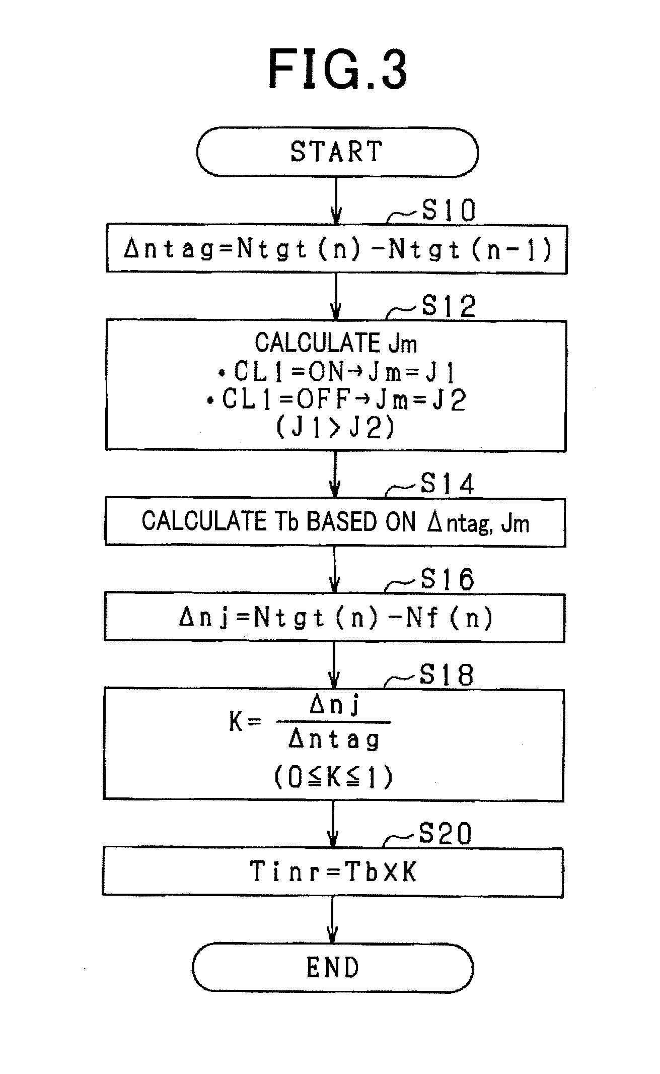
[0069]A description will be given of the control device for an electric rotary machine according to a second exemplary embodiment. A to difference between the control device according to the second exemplary embodiment and the control device according to the first exemplary embodiment will be explained with reference to drawings. As shown by the flow chart in FIG. 6, the control device according to the second exemplary embodiment uses another method of setting the reflection coefficient K. The same processes between the flow chart shown in FIG. 6 and the flow chart shown in FIG. 3 will be refereed with the same step numbers for brevity.

[0070]After completion of the process in step S16, the operation flow goes to step S22. In step S22, it is judged that whether a logical sum of a condition in which each of the target rotation speed change rate Δntag and the judgment difference Δnj is a positive value, and condition in which each of the target rotation speed change rate Δntag and the ...

third exemplary embodiment

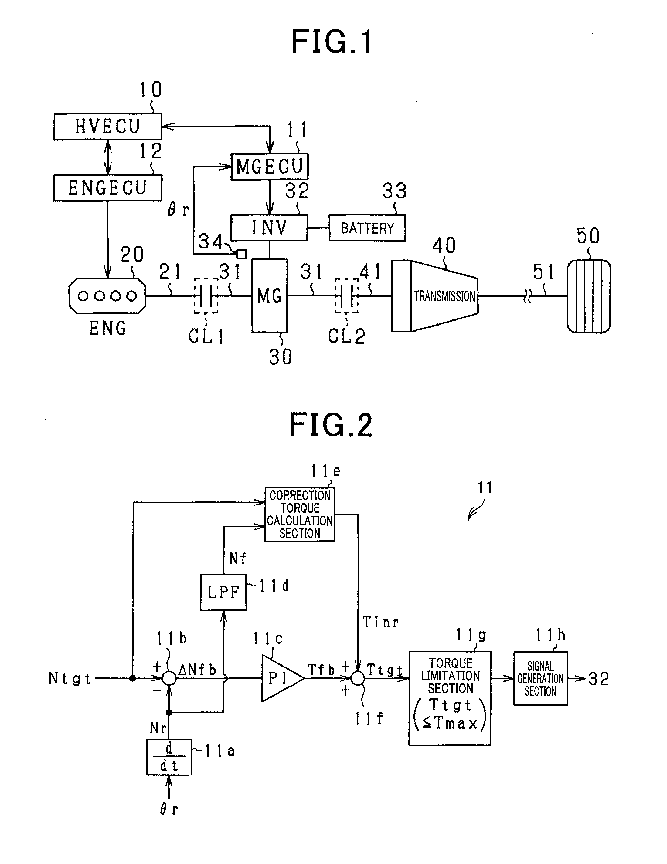
[0073]A description will be given of the control device for an electric rotary machine according to a third exemplary embodiment. A difference between the control device according to the third exemplary embodiment and the control device according to the first exemplary embodiment will be explained with reference to drawings. In the third exemplary embodiment, the MGECU 11′ having the structure shown in FIG. 7 performs the control method of adjusting the rotation speed of the motor generator 30 as an electric rotary machine. In FIG. 7, the same structure and processes of the MGECU 11 shown in FIG. 2 previously described will be referred to as the same reference characters for brevity. In the MGECU 11′ of the control device according to the present exemplary embodiment, the filter 11d is called to as a first filter.

[0074]A second filter 11i inputs the target rotation speed Ntgt. In the control device for an electric rotary machine according to the third exemplary embodiment, the secon...


PUM


Abstract

A MGECU in a control device mounted on a vehicle has a feedback control section, a correction torque calculation section, an instruction torque calculation section. The feedback control section calculates a torque to be used for performing a feedback control of an actual rotation speed to follow a target rotation speed. The correction torque calculation section calculates a correction torque based on a change rate of the target rotation speed and inertia of a rotary body which includes the motor generator. When the target rotation speed is changed to decrease a difference between the target rotation speed and the actual rotation speed, the correction torque calculation section reduces the correction torque. The instruction torque calculation section adds the torque calculated by the feedback control section and the correction torque calculated by the correction torque calculation section in order to obtain the instruction torque to be used for the motor generator.

Description

CROSS-REFERENCE TO RELATED APPLICATION[0001]This application is related to and claims priority from Japanese Patent Application No. 2014-83425 filed on Apr. 15, 2014, the contents of which are hereby incorporated by reference.BACKGROUND OF THE INVENTION[0002]1. Field of the Invention[0003]The present invention relates to control devices capable of controlling electric rotary machines as a drive power source of motor vehicles.[0004]2. Description of the Related Art[0005]For example, a patent document, Japanese patent laid open publication No. 2002-27611 shows a control device for controlling such an electric rotary machine. The control device is applied to a motor vehicle equipped with an electric rotary machine and an internal combustion engine which are used as drive power sources of a motor vehicle. This control device instructs the electric rotary machine to increase its generated torque when receiving a start request to start the internal combustion engine while the motor vehicl...

Claims


Application Information

Patent Timeline
IPC IPC(8): B60L15/20B60W10/06B60W10/08B60W20/00B60W10/02B60L50/16
CPCB60L15/20B60W20/40B60W10/02B60W10/08Y10S903/93B60W2510/083B60W2710/021B60W2710/0666Y10S903/906B60W10/06B60W20/00B60W30/184B60K2006/4825B60W2050/001B60W2510/0216B60W2510/088B60W2710/081B60W2710/082B60W2710/083B60L2210/40B60L2220/14B60L2240/12B60L2240/421B60L2240/423B60L2240/441B60L2240/443B60L2240/80B60L2260/26B60L2270/145Y02T10/70B60L50/16B60L58/12Y02T10/62Y02T10/64Y02T10/72Y02T10/7072
Inventor KAWASAKI, SHINGO
Owner DENSO CORP
Why Eureka
Try Eureka