
Optimization of retransmission timeout boundary

a timeout boundary and retransmission technology, applied in the field of data transmission, can solve the problems of retransmission timeout (“rto”) violation, unnecessary congestion of the network, delay of the flow of conversation between the nodes,

Active Publication Date: 2015-10-08
TEXAS STATE UNIVERSITY
View PDF18 Cites 10 Cited by
  • Summary
  • Abstract
  • Description
  • Claims
  • Application Information

AI Technical Summary

Benefits of technology

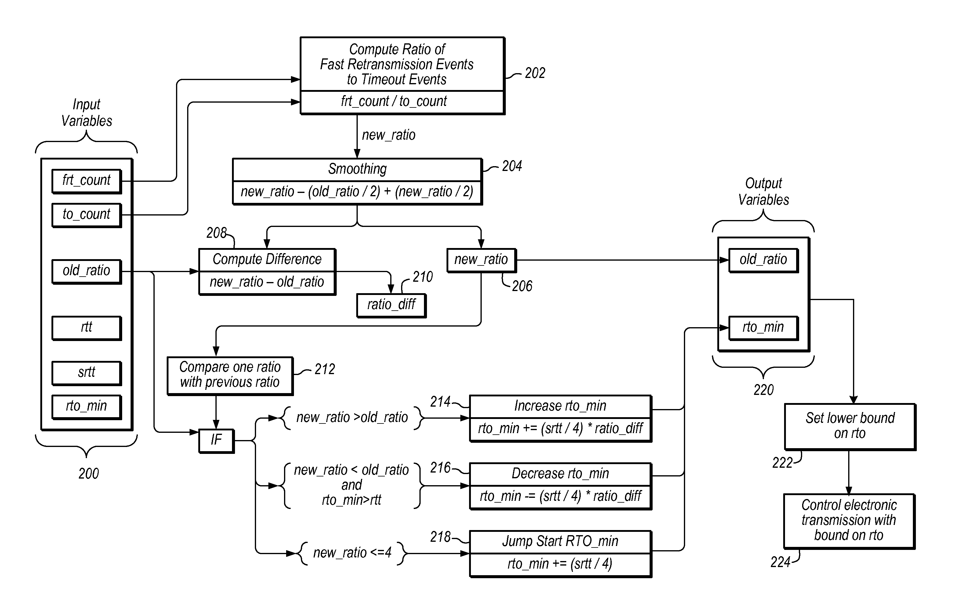
The patent text describes a system and method for optimizing retransmission mechanisms in network transmissions. The system includes a controller and a network of nodes. The controller determines bounds on the time it takes for a retransmission request to be acknowledged, and uses these bounds to control the timing of electronic transmissions between the nodes. The system can adapt the coefficients of algorithms to estimate the time it takes for a retransmission request to be acknowledged, based on the network parameters observed during the transmission. The technical effect of the patent is to improve the efficiency and reliability of network transmissions by optimizing the retransmission timeout mechanism.

Problems solved by technology

If transmitting nodes use timers that are too short, packets may be retransmitted before they are received by the corresponding node, thereby congesting the network unnecessarily.
Conversely, if transmitting nodes use timers that are too long, lost or corrupted packets may not be retransmitted in a timely fashion, thereby delaying the flow of the conversation between the nodes.
When a retransmission timer expires due to an unacknowledged transmission, a retransmission timeout (“RTO”) violation may occur.

Method used


Image

  • Optimization of retransmission timeout boundary
  • Optimization of retransmission timeout boundary
  • Optimization of retransmission timeout boundary

Examples


Embodiment Construction

[0027]In various embodiments, communication parameters are optimized by dynamically computing a lower bound for an internet protocol data retransmission timer based on statistics of the observed network characteristics. Characteristics may be observed, for example, by a control device, such as a programmable logic controller. A minimum value of a re-transmission timeout (RTO) for a data transmission may be varied based optimization calculations. In some embodiments, the lower bound is applied to a packet retransmission mechanism in connection-oriented Internet Protocol (IP) transport protocols, such as SCTP and TCP. (A minimum value of a RTO may be referred to herein as “RTO_min”).

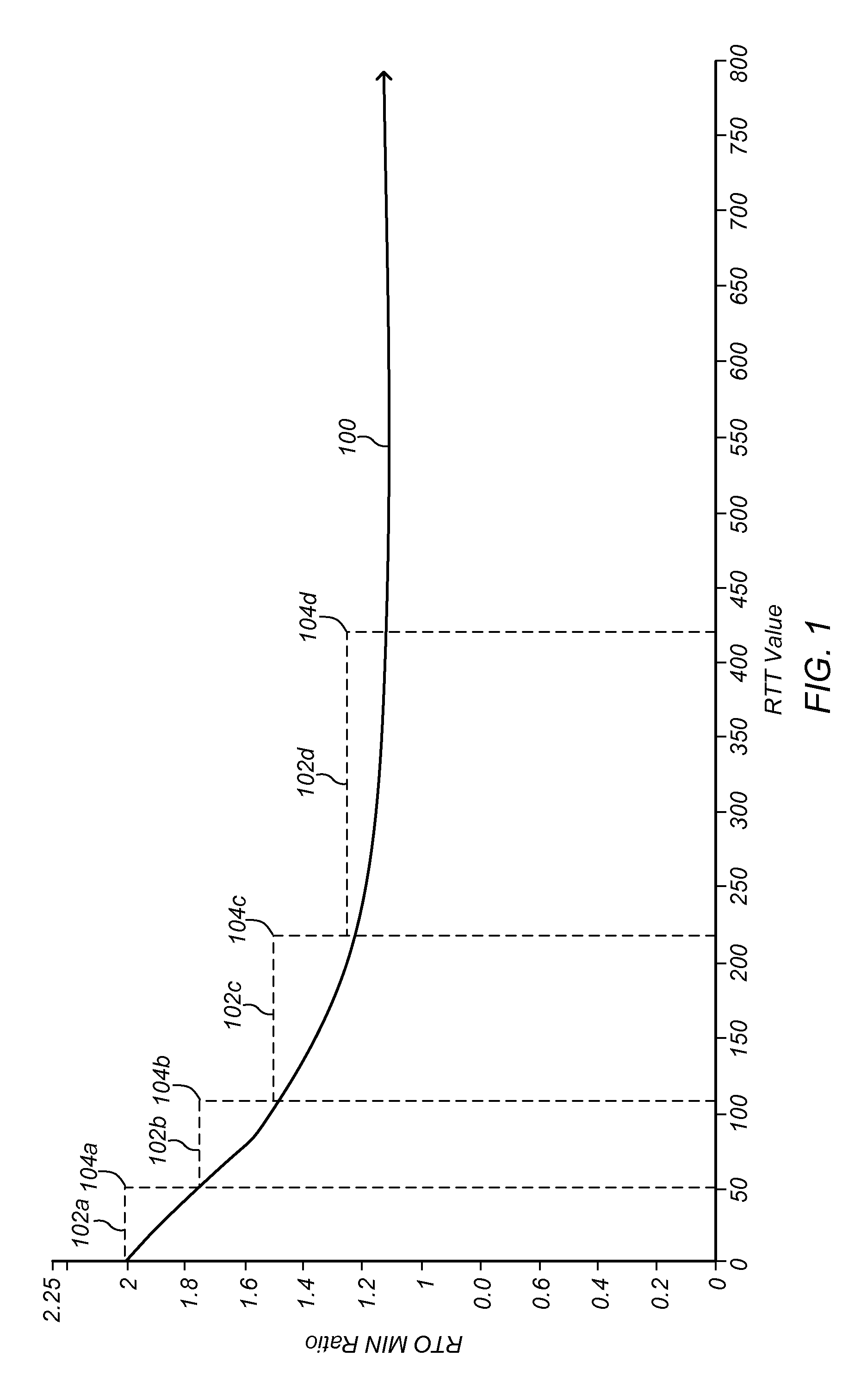
[0028]In some embodiments, an RTO_min is dynamically determined based on observed, historical values of RTT. RTT values may be used directly, or may be processed using smoothing filters or other algorithms such as Jacobson's Algorithm. FIG. 1 is a graph illustrating an RTO_min that varies based on historic...


PUM


Abstract

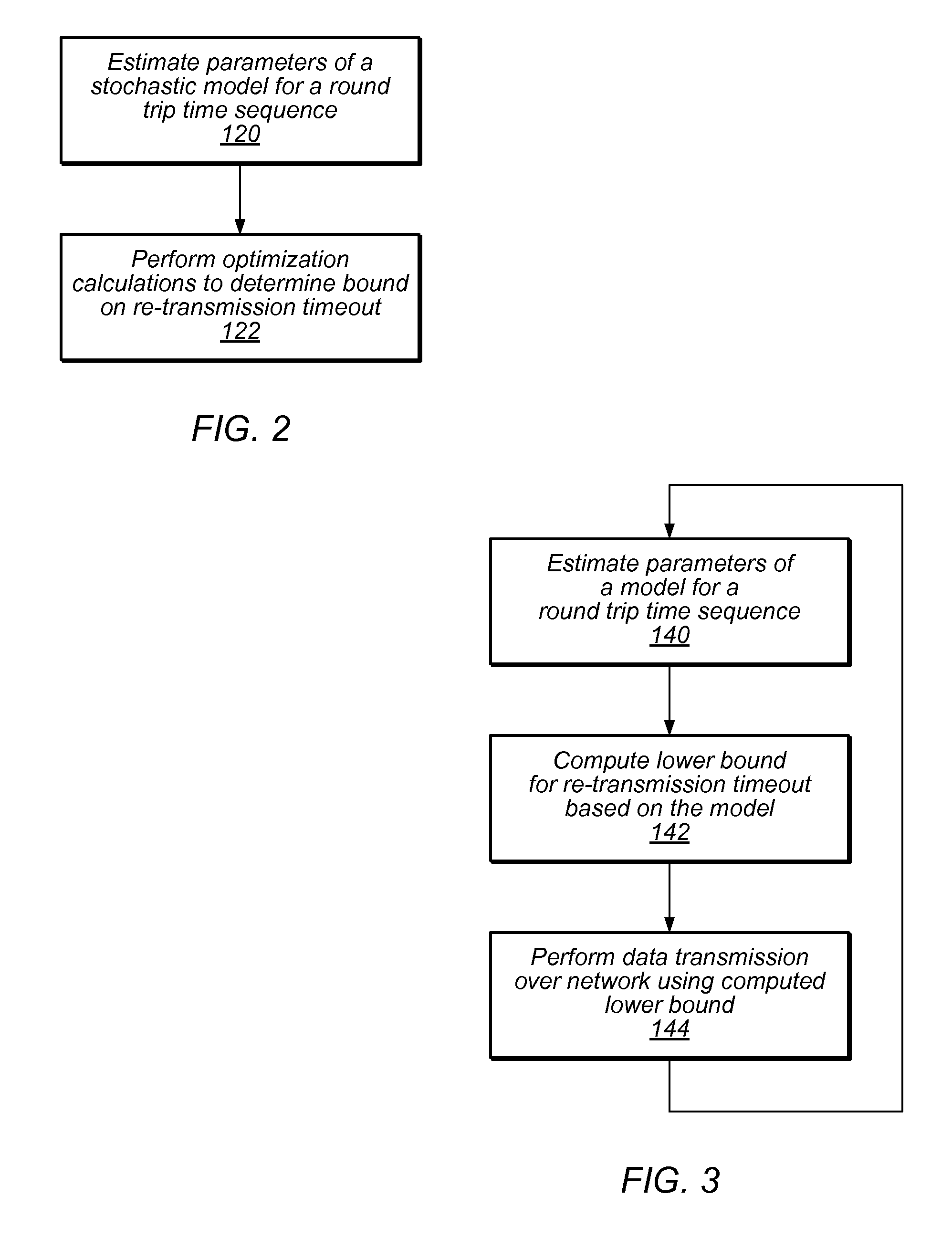
A method includes estimating a parametric model for a round-trip time sequence for an electronic transmission over a network. Optimization calculations may be performed to dynamically determine a bound (for example, a lower bound) on re-transmission timeout for an electronic transmission to be conducted over the network.

Description

BACKGROUND[0001]1. Field[0002]This invention relates to data transmission. More particularly, the invention relates to methods and systems for timing of re-transmissions in network communications.[0003]2. Description of the Related Art[0004]Connection-oriented IP transport protocols, such as the Stream Control Transmission Protocol (“SCTP”) or Transport Control Protocol (“TCP”), use retransmission mechanisms to ensure reliable delivery of a user's data from the transmitting node (near end) to the corresponding node (far end). These retransmission mechanisms involve monitoring a timer which is set upon certain types of transmissions (for TCP “segments” or for SCTP “chunks”). If the timer(s) expire before the corresponding node acknowledges receipt of the packets, the transmitting node may conclude that the previous transmission(s) were lost or corrupted, and may re-send the affected packets using one or more retransmission mechanisms.[0005]Judicious use of retransmission mechanisms i...

Claims


Application Information

Patent Timeline
Patent Type & Authority Applications(United States)
IPC IPC(8): H04L12/26H04L1/08
CPCH04L1/08H04L43/0852H04L41/142H04L43/0864H04L43/0882H04L41/12H04L69/02H04L69/28H04L1/188H04L1/1887H04L41/40H04L43/20
Inventor MCCLELLAN, STANPENG, WUXUGONZALEZ, EDUARDO
Owner TEXAS STATE UNIVERSITY
Learn More