
Portable Power Bank

a power bank and portability technology, applied in the direction of dc-dc conversion, transportation and packaging, battery arrangement for several simultaneous batteries, etc., can solve the problems of large energy loss and heat generated during energy transfer, the number of battery cells chained in conventional power banks is therefore being limited to avoid the risk of electrical fire, and the charging rate of some electronic devices is low, so as to achieve the effect of slow charging rate and heavy load in electric charge flow

Inactive Publication Date: 2015-10-08
LAUSDEO
View PDF6 Cites 12 Cited by
  • Summary
  • Abstract
  • Description
  • Claims
  • Application Information

AI Technical Summary

Benefits of technology

The present invention is related to a portable power bank that uses lithium-ion cells to store energy. These cells are connected in series, which allows for faster charging and higher DC input voltage compared to conventional power banks. The technical effect achieved by this design is improved safety, efficiency, and rapid charging of the power bank's cells.

Problems solved by technology

Large quantities of energy lost and heat generated during energy transfer are inevitable in conventional power banks; the number of battery cells chained in conventional power banks is therefore being limited to avoid the risk of electrical fires.
Once the charging current flowing out from the power bank is also invariable, the constant voltage of a power bank may lead to a problem that the charging rate is low for some electronic devices.
These types of batteries comprise several defects such as severe memory effect, toxin materials, and short battery life.

Method used


Image

  • Portable Power Bank
  • Portable Power Bank

Examples


Embodiment Construction

[0015]In a general aspect, at least one embodiment in accordance with the present invention relates to a portable power bank. More particularly, at least one embodiment relates to a portable power bank characterized by a high charging rate. The embodiments and drawings provided here show different aspects of the present invention. However, the present invention are neither limited to any embodiment nor drawing thereof.

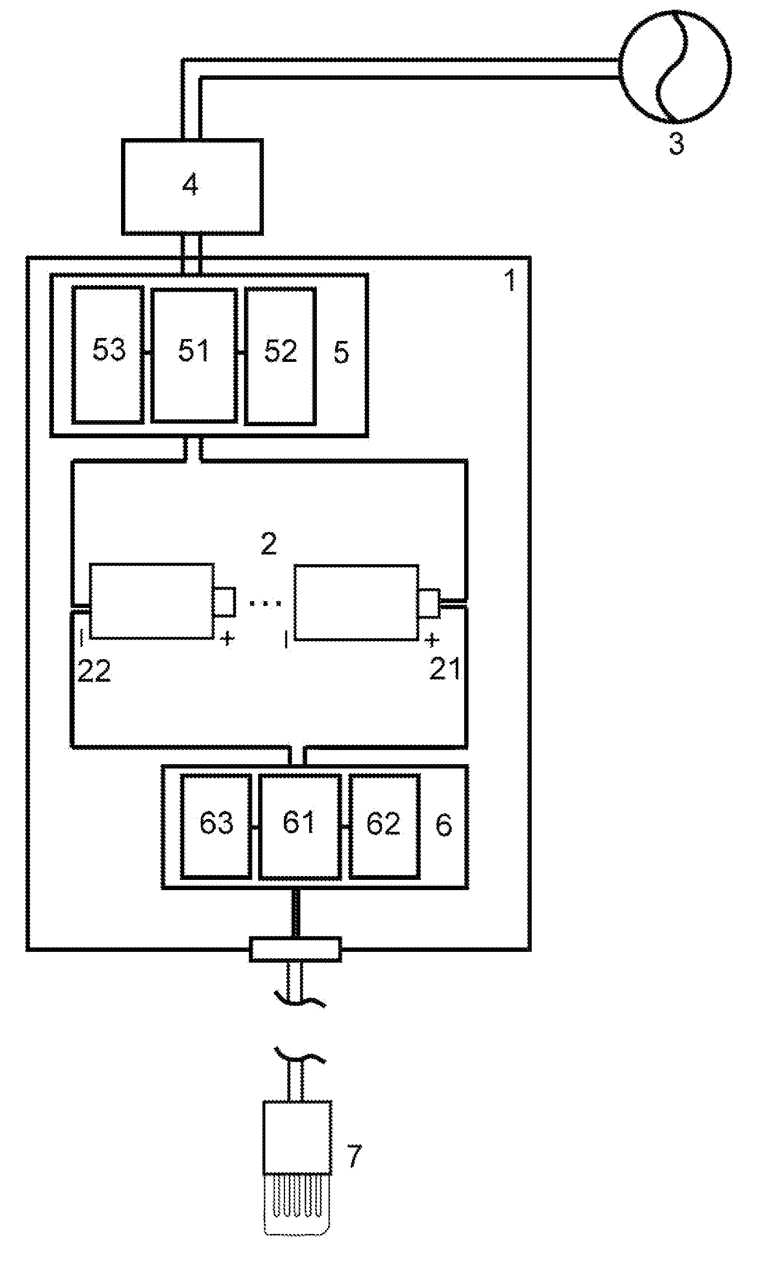
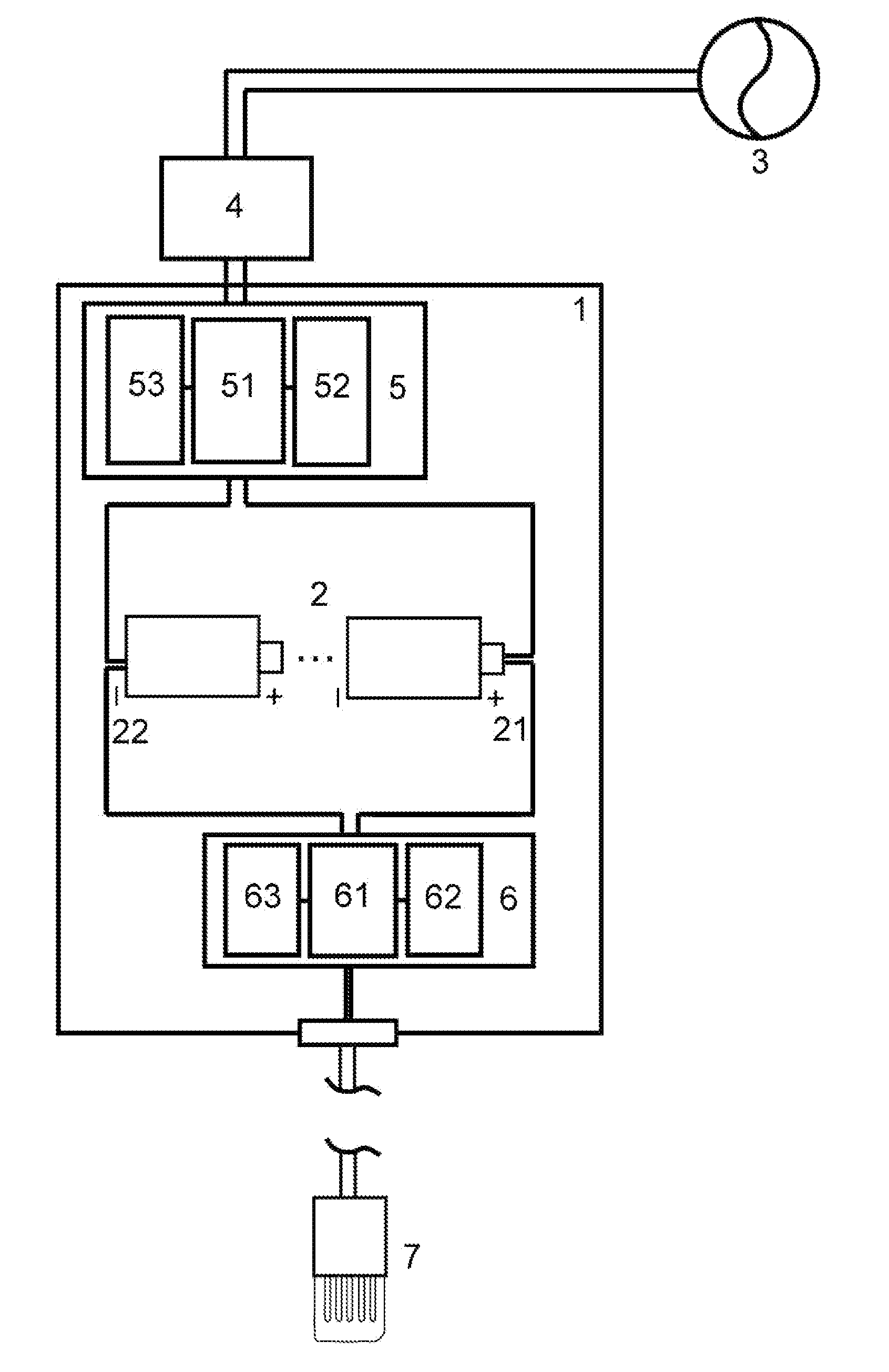
[0016]The FIGURE is a schematic diagram illustrating a portable power bank in accordance with at least one embodiment of the present invention. In the FIGURE, an AC power source 3 provides AC currents to a rectifier 4, and the rectifier 4 converts the AC currents into charging currents and transfers the charging currents to a portable power bank 1, wherein the charging currents are DC currents.

[0017]In some embodiments of the FIGURE, the portable power bank 1 comprises a first control module 5, connected to the rectifier 4, for receiving the charging currents; the firs...


PUM


Abstract

The present invention relates to a portable power bank comprising a battery pack, a first control module and a second control module, wherein the battery pack further comprises at least two cells connected in series, and wherein the first control module and the second control module both electrically connected to a first terminal and a second terminal of the battery pack; the first controller is configured for regulating the DC input voltage for charging the battery pack and the second controller is configured for regulating the DC output voltage for charging an external device.

Description

TECHNICAL FIELD[0001]At least one embodiment in accordance with the present invention relates to a portable power bank. More particularly, at least one embodiment relates to a portable power bank characterized by a rapid charging rate.DESCRIPTION OF THE RELATED ART[0002]A power bank is configured for supplying electric energy to electronic devices. In recent years, electronic devices such as cell phones and tablets have induced a massive transformation in the lifestyles nowadays. With the growing dependence on these electronic devices, the demand for high capacity batteries has increased for supporting a full day's use; however, to elevate the capacity of a battery may simultaneously augment the weight and the physical volume. In this case, a backup battery may be a solution; nevertheless, the current fashion tenting to use embedded batteries instead of removable batteries subsequently stimulates the development of power banks as an alternative method.[0003]Conventional power banks ...

Claims


Application Information

Patent Timeline
Patent Type & Authority Applications(United States)
IPC IPC(8): H02J7/04H02J7/00H02J7/02
CPCH02J7/0013H02J7/04H02M3/1582H02J7/342H02J7/02H02J2207/20H02M1/10
Inventor LIN, MING-CHIEHYANG, CHUN-LIANGCHANG, WEN-HSIANGKUO, JUNGHSU, MENG-KWEI
Owner LAUSDEO
Learn More