
Wavelength-maintaining fabry-perot laser diode and optical transmitter including same

Inactive Publication Date: 2015-10-08
KOREA ADVANCED INST OF SCI & TECH
View PDF4 Cites 0 Cited by
  • Summary
  • Abstract
  • Description
  • Claims
  • Application Information

AI Technical Summary

Benefits of technology

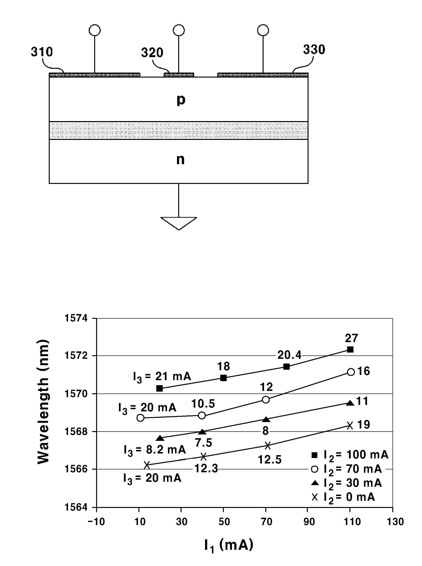
The patent introduces a new design that allows for better wavelength keeping and intensity and phase modulation in a more versatile way. This is achieved by adding a section for phase shift into a general F-P LD structure. The technical effect of this is that it provides better flexibility for selecting the wavelength of light that needs to be controlled, which is useful in a variety of applications.

Problems solved by technology

As noted above, as noise of the received optical signal is changed in response to the detuning, the physical properties deteriorate due to changed detuning when external environments such as temperature are changed even if operated under an optimal condition.
As a result, a high output powered BLS (100) must be used, which disadvantageously increases a power consumption of entire system to increase the price.
Meanwhile, although almost no influence is received by detuning when an RSOA is used, the RSOA lags behind in price competitiveness over the F-P LD to inevitably use a TEC, resulting in increased power consumption to a great extent.
However, the triple contact F-P LD according to the prior art cannot satisfy a scope of wavelength keeping capable of coping with a broad temperature change of an actual field when a change rate (0.1 nm / ° C.) in response to the temperature is considered.
At this time, when the external temperature is changed to change the oscillation wavelength of the laser, laser characteristics are changed, and the F-P LD returns to multiple mode, and becomes difficult to be used for WDM.
However, the reflective semiconductor optical amplifier must be attached with a TEC because the reflective semiconductor optical amplifier is narrow in operating wavelength scope and high in operating current.
Although this may be thought as one of subclasses of wavelength tracking F-P LD, it is difficult to remove the TEC.
However, an external modulator used for this purpose is disadvantageously expensive, and low in competitiveness in terms of maintenance / repair.

Method used


Image

  • Wavelength-maintaining fabry-perot laser diode and optical transmitter including same
  • Wavelength-maintaining fabry-perot laser diode and optical transmitter including same
  • Wavelength-maintaining fabry-perot laser diode and optical transmitter including same

Examples


Embodiment Construction

[0047]Various exemplary embodiments will be described more fully hereinafter with reference to the accompanying drawings, in which some exemplary embodiments are shown.

[0048]The present inventive concept may, however, be embodied in many different forms and should not be construed as limited to the example embodiments set forth herein. Rather, the described aspect is intended to embrace all such alterations, modifications, and variations that fall within the scope and novel idea of the present disclosure.

[0049]It will be understood that, although the terms first, second, etc. may be used herein to describe various elements, these elements should not be limited by these terms. These terms are only used to distinguish one element from another. For example, a first region / layer could be termed a second region / layer, and, similarly, a second region / layer could be termed a first region / layer without departing from the teachings of the disclosure.

[0050]It will be understood that when an e...


PUM


Abstract

A wavelength tracking Fabry-Perot Laser Diode (F-P LD), and an optical transmitter including the same are disclosed, the wavelength keepable F-P LD including a gain section configured to provide and modulate a gain using an injected first current; and a phase shift / modulation section configured to vary wavelength relative to oscillation mode of light advanced from the gain section by injected second current or voltage and to modulate phases.

Description

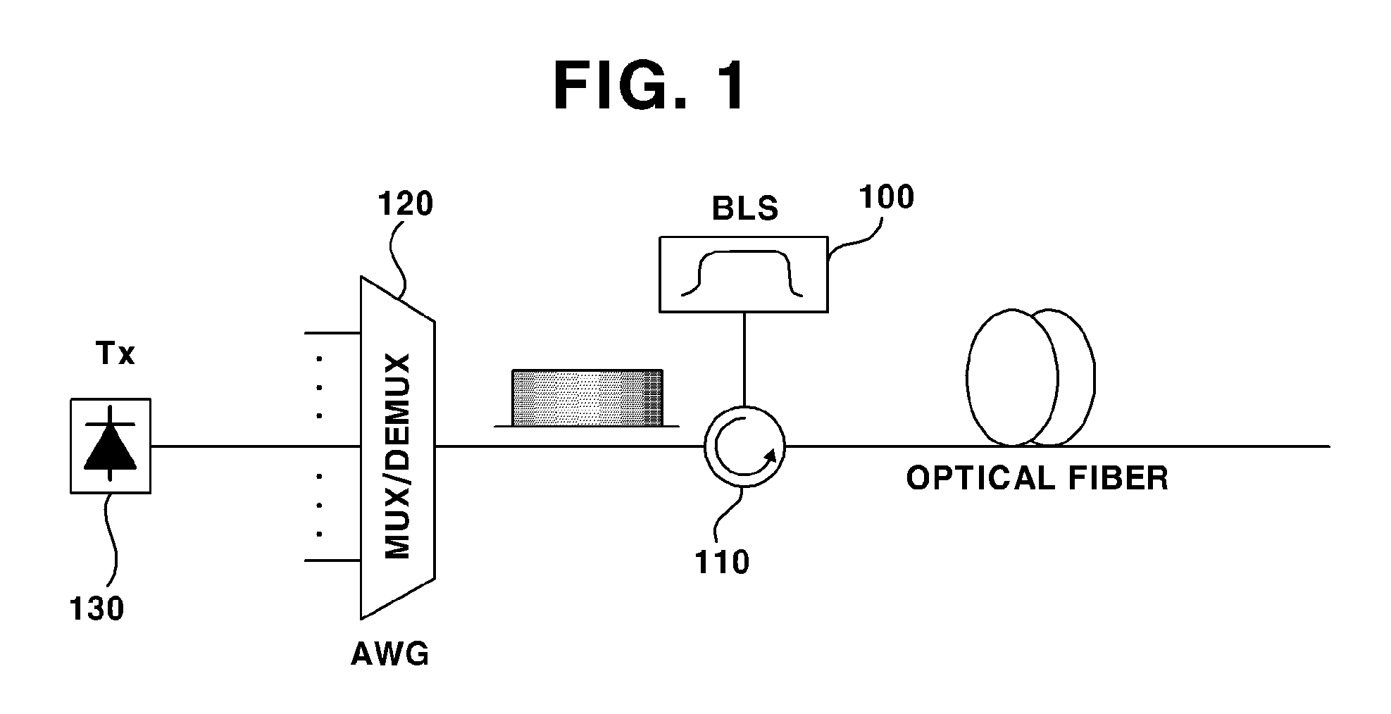
TECHNICAL FIELD[0001]The present invention relates to a semiconductor laser diode, and more particularly to a wavelength tracking Fabry-Perot Laser Diode (F-P LD), and an optical transmitter including a wavelength tracking F-P LD using an optical communication system.BACKGROUND OF THE INVENTION[0002]In general, a WDM network (Wavelength Division Multiplexed-Optical Network) has become recognized as an ultimate network capable of coping with explosive network traffic increase due to advantages capable of providing bandwidth catering to recently explosively increasing bandwidth demand.[0003]FIG. 1 is a schematic block diagram illustrating a general WDM-PON system.[0004]A broadband light outputted from a BLS (Broadband Light Source, 100 is spectrum-divided (filtered) after passing a demultiplexing AWB (Arrayed Waveguide Grating, 120) by passing through an optical circulator, 110). The spectrum-divided light is injected into an optical transmitter (Tx, 130). In general, the optical tran...

Claims


Application Information

Patent Timeline
IPC IPC(8): H01S5/026H01S5/0625H01S5/062H01S5/042
CPCH01S5/0265H01S5/06246H01S5/06255H01S5/0425H01S5/4012H01S5/4087H01S2301/02H01S5/06256
Inventor LEE, CHANG-HEEKIM, JOON-YOUNGMUN, SANG-ROKYOO, SANG-HWASEO, BYUNGILKYE, MYEONGGYUNCHANG, JIAN
Owner KOREA ADVANCED INST OF SCI & TECH
Learn More