
Method of manufacturing or repairing a pipe

a manufacturing or pipe technology, applied in the direction of coating, coating, application, etc., can solve the problems of difficult to achieve a good surface finish in the machined o-ring groove, especially o-ring damage, etc., and achieve the effect of easy manufacturing of the composite material pipe portion

Inactive Publication Date: 2015-10-08
AIRBUS OPERATIONS LTD
View PDF5 Cites 2 Cited by
  • Summary
  • Abstract
  • Description
  • Claims
  • Application Information

AI Technical Summary

Benefits of technology

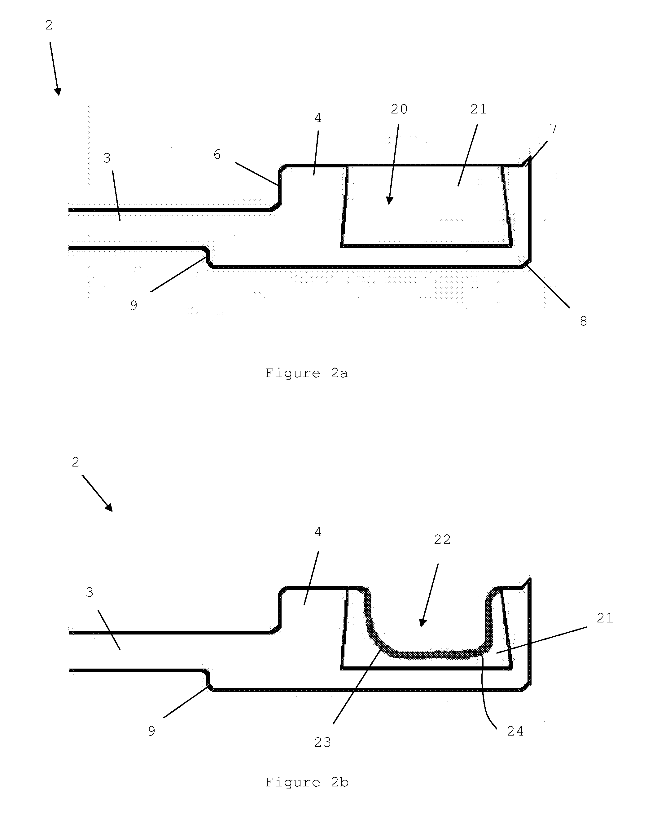
The patent text describes a method for improving the surface quality of a groove or channel in a composite material pipe. This is achieved by using a filler material that can be easily finished compared to the composite material used for the pipe, which makes the manufacturing process easier. The filler material is applied to the internal surface of the channel and then cured, which helps to keep it in place and provides a smooth surface finish. The channel is also designed with inwardly angled edges, which helps to keep the filler material in the channel and provides a larger area for adhesion. Using an integral end fitting also makes the manufacture of the pipe easier, as it can be done in one step. Overall, this method allows for better quality pipes to be produced more efficiently.

Problems solved by technology

A problem with using composite material pipes is that it is difficult to achieve a good surface finish in a machined O-ring groove.
This causes the O-ring, especially if it is made from a compressive material such as rubber, to become damaged from the exposed composite fibres and surface roughness in the groove.

Method used


Image

  • Method of manufacturing or repairing a pipe
  • Method of manufacturing or repairing a pipe
  • Method of manufacturing or repairing a pipe

Examples


Embodiment Construction

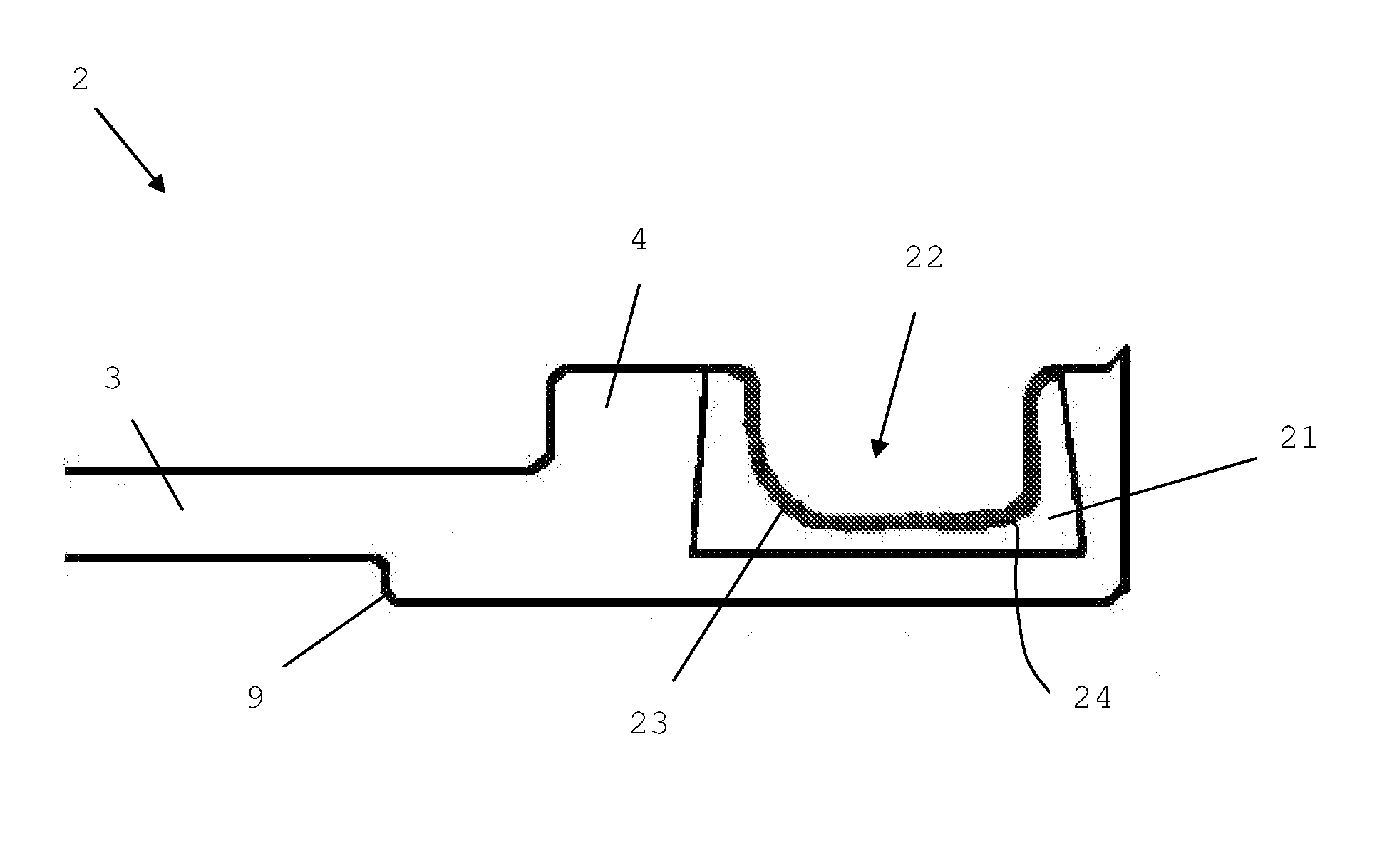
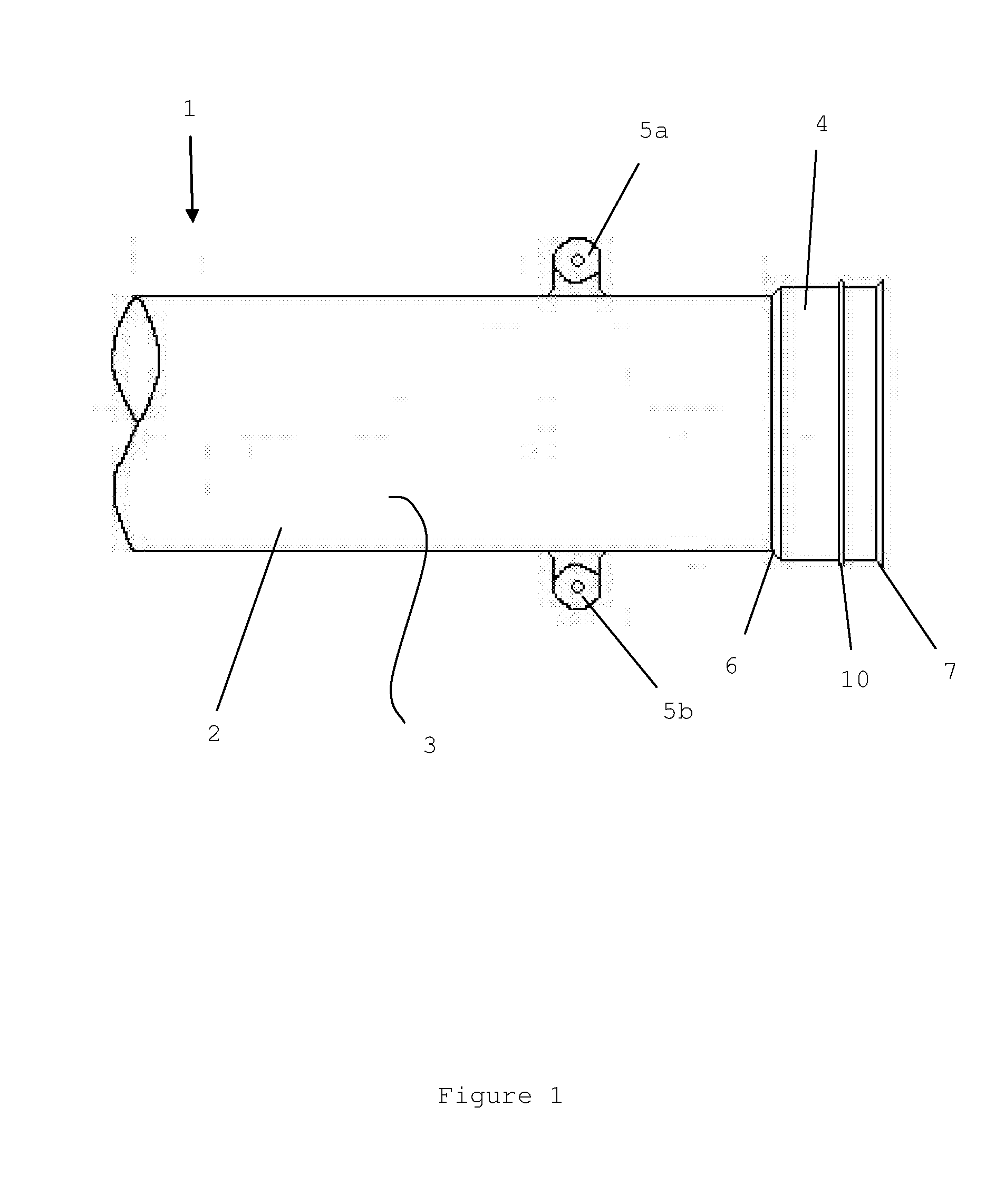
[0042]FIG. 1 shows a side view of a portion 2 of a composite material pipe 1 according to a first embodiment of the invention.

[0043]The pipe portion 2 is formed by filament winding of carbon fibre composite material and has an integral end fitting 4 on one end, with a slightly larger diameter of 3 inches (76 mm), than the rest 3 of the pipe portion 2. The pipe portion 2 also has two attachment points 5a, 5b used for attaching electrical bonding leads (not shown) to the pipe, for example in an aircraft.

[0044]The end fitting 4 comprises a pipe chamfered portion 6 where the end fitting 4 meets the rest 3 of the pipe portion 2. The end fitting 4 also has an end chamfered portion 7 at the far end of the end fitting 4.

[0045]The end fitting 4 is provided with an O-ring groove (22, although not labelled in FIG. 1 for clarity) with a compressive rubber O-ring 10 in it. The O-ring 10 and groove extend around the circumference of the end fitting 4 at a location towards the far end of the end f...


PUM

PropertyMeasurementUnit
Thicknessaaaaaaaaaa
Diameteraaaaaaaaaa
Diameteraaaaaaaaaa

Abstract

A method of manufacturing or repairing a pipe including: providing a pipe portion having a channel running along a surface of the pipe portion, wherein the channel has an internal surface; placing a filler material against the internal surface of the channel, and removing some of the filler material to provide a groove in the channel.

Description

BACKGROUND OF THE INVENTION[0001]The present invention concerns manufacturing or repairing a pipe. More particularly, but not exclusively, this invention concerns a method of manufacturing or repairing a pipe where the pipe has a groove running along a surface of the pipe, the groove being for accommodating an O-ring seal. The invention also concerns a pipe or pipe portion.[0002]Metallic pipes with O-ring grooves are traditionally manufactured with a separate end fitting. The end fitting may have a larger diameter than the rest of the pipe. The O-ring groove is machined out of the end fitting and is smoothed to give a good surface finish. It is possible to achieve a good surface finish in the metallic pipe. A rubber O-ring is then placed in the groove.[0003]However, in order to save weight, especially on an aircraft, composite materials are increasingly being used. Composite material pipes can be manufactured using filament windings. A problem with using composite material pipes is ...

Claims


Application Information

Patent Timeline
IPC IPC(8): F16L21/035B29D23/00
CPCF16L21/035Y10T29/49719B29D23/003B29C70/766B29C73/02
Inventor VAGHELA, NARESH
Owner AIRBUS OPERATIONS LTD
Learn More