
Unified orbit and attitude control for nanosatellites using pulsed ablative thrusters

a nanosatellite and pulsed technology, applied in the field of spacecraft orbit and attitude control, can solve problems affecting positively on its performance, and achieve the effects of saving mass and internal volume, affecting positively on its performance, and full utilization of pulsed nature of pats

Active Publication Date: 2015-10-08
KRONHAUS IGAL +1
View PDF37 Cites 11 Cited by
  • Summary
  • Abstract
  • Description
  • Claims
  • Application Information

AI Technical Summary

Benefits of technology

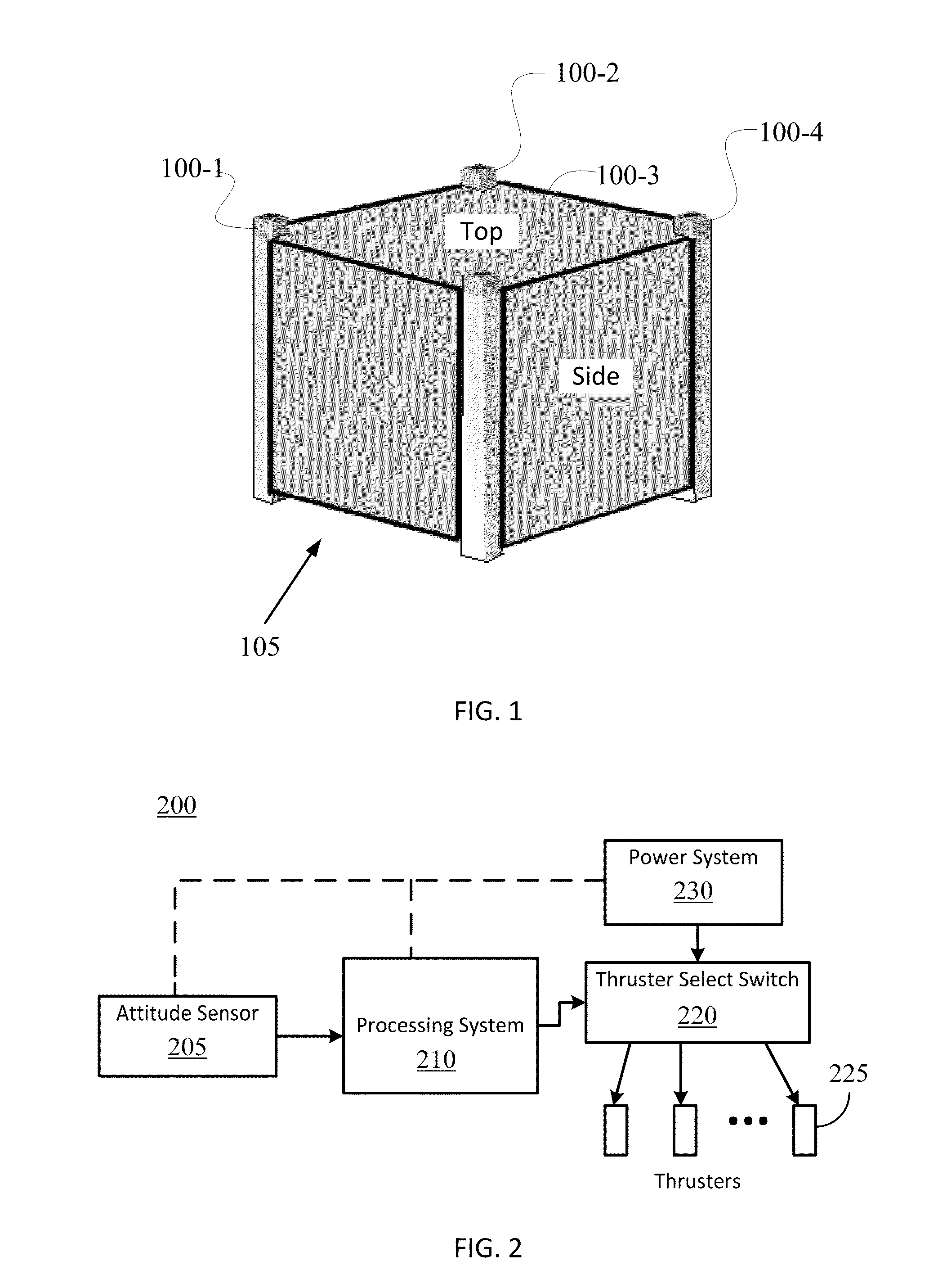
[0007]The spacecraft body of the nanosatellite can be configured so that the PATs appear embedded within the spacecraft body extremities (e.g., edges of a common cube-shaped spacecraft body), enabling the original shape of the spacecraft body to be maintained and saving mass and internal volume. Control electronics of the processing system and other sensors may be incorporated in or on the spacecraft body as suitable for the conditions in which the satellite is operated.
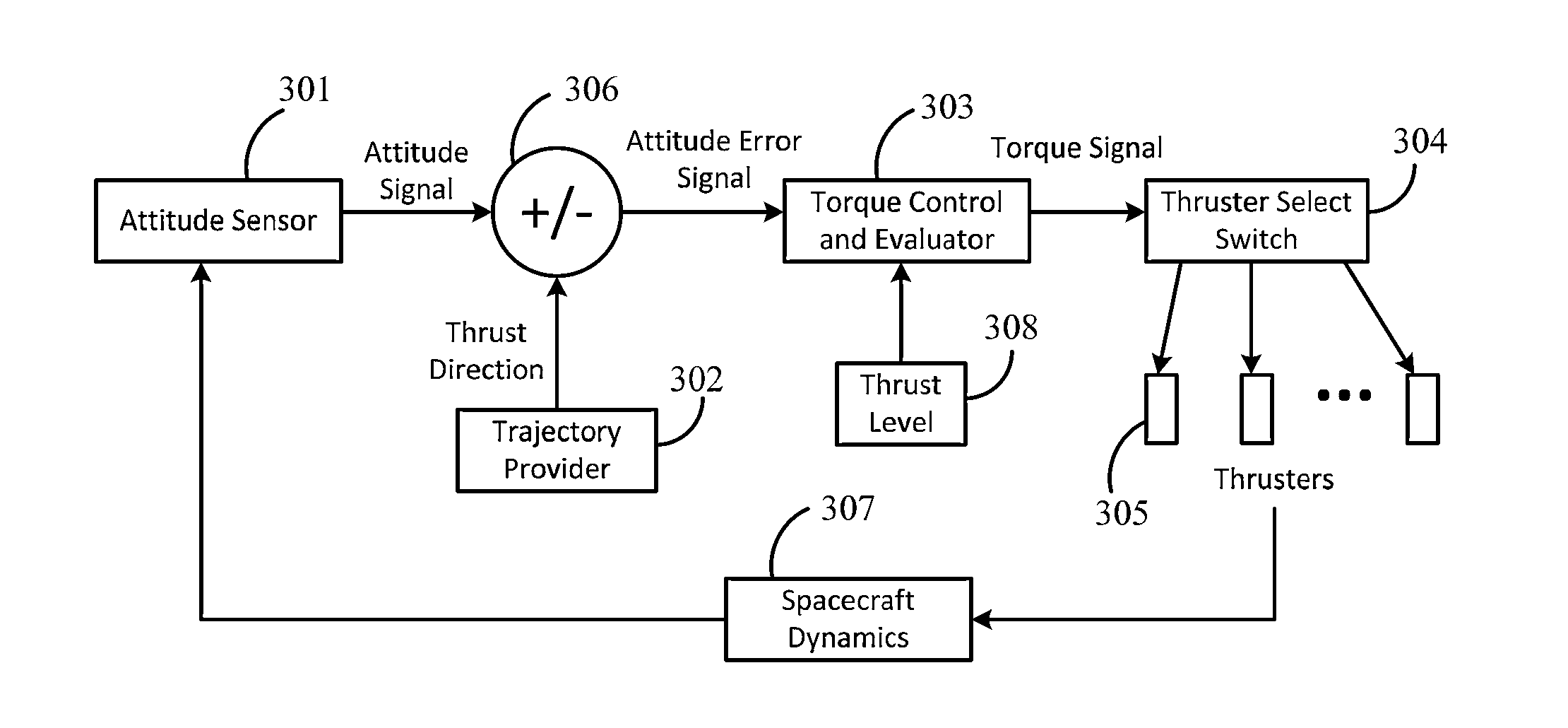
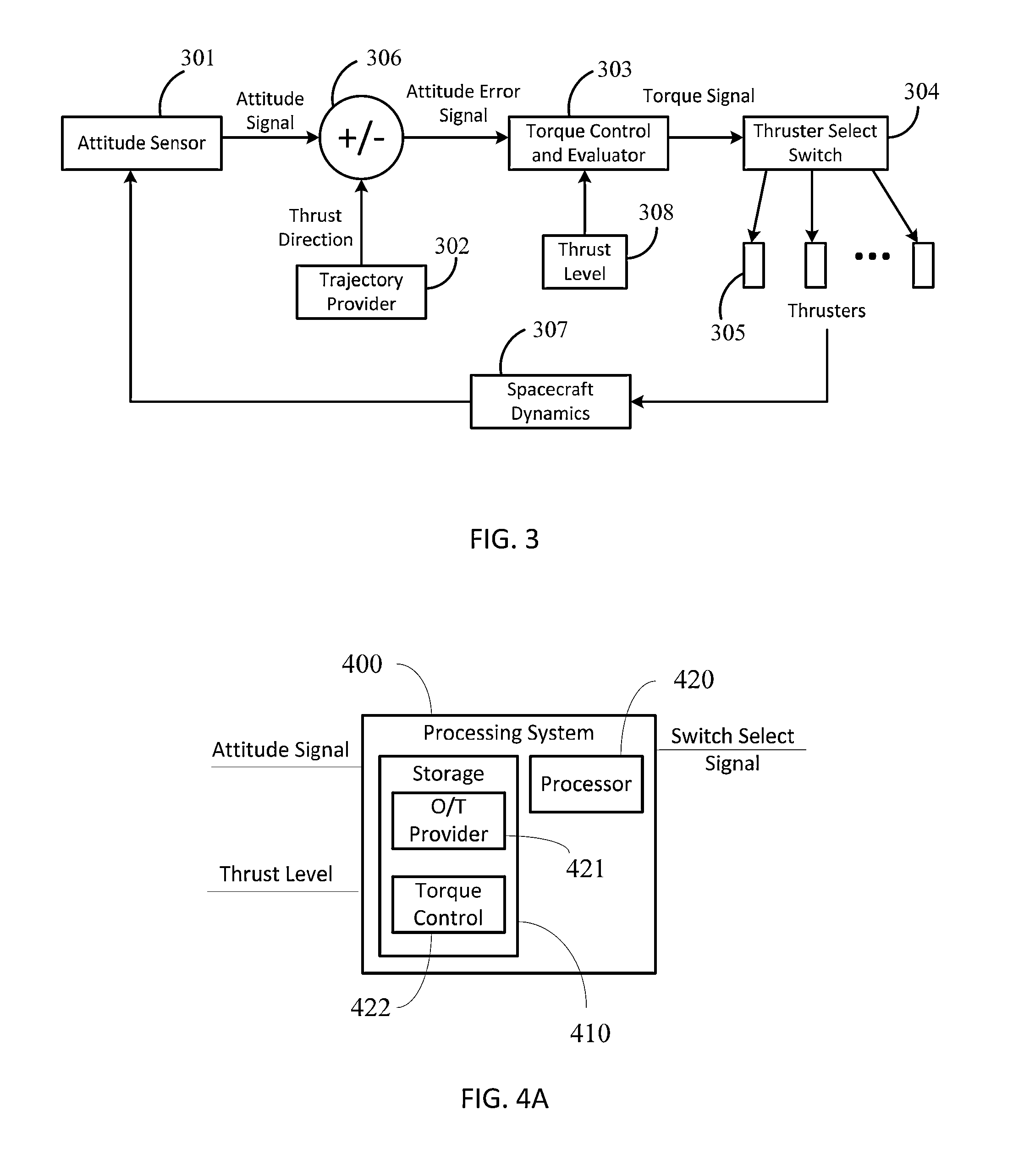
[0008]According to an embodiment of the unified attitude and orbit control, the attitude sensor signal is compared by the processing system of the spacecraft to a desired spacecraft attitude, calculated by the processing system based on orbit position and predicted trajectory. The comparison generates an error signal used to calculated a corrective torque, which is evaluated by the processing system to determine a single thruster of the PAT assembly which is to be operated at full thrust at any given time or pulse. Advantageously, the full utilization of the pulsed nature of the PATs can be carried out, where the actuation is performed in discrete unit or pulses. Thus, the maximum amount of energy is available to power the thruster, affecting positively on its performance.

Problems solved by technology

Thus, the maximum amount of energy is available to power the thruster, affecting positively on its performance.

Method used


Image

  • Unified orbit and attitude control for nanosatellites using pulsed ablative thrusters
  • Unified orbit and attitude control for nanosatellites using pulsed ablative thrusters
  • Unified orbit and attitude control for nanosatellites using pulsed ablative thrusters

Examples


Embodiment Construction

[0016]A pulsed ablative thruster (PAT)-based combined, or “unified”, orbit-and-attitude control system is provided. In certain implementations, the unified orbit-and-attitude control system for PAT-based propulsion systems may avoid the power, mass, and volume penalties of having an attitude control system (e. g. momentum wheels) separate from the propulsion system. In addition, some of the described configurations facilitate efficient use of power (and fuel).

[0017]Orbital correction maneuvers are carried out by satellites to keep a line of sight with each other and maintain a formation-flying configuration for more than a few weeks.

[0018]For nanosatellites, with total mass of less than few kilograms, executing the required orbital velocity change ΔV (10-100 m / s) using conventional chemical propulsion can be impractical, as the propulsion system occupies a large fraction of the available volume and mass. Instead, PATs such as pulsed plasma thrusters or vacuum arc thrusters can be us...


PUM


Abstract

Systems and methods for orbit and attitude control of nanosatellites are provided. A spacecraft can be equipped with a plurality of pulsed ablative thrusters (PAT), mounted on at least one of the spacecraft body orientations. The PATs are integrated with the spacecraft structure. The actual spacecraft attitude is measured by a sensor and compared with the desired thrust direction. In order to reduce attitude errors, a control system is used to determine the firing sequence of thrusters. During maneuvering the thrusters are continuously being fired. To conserve energy a thrust switch control is utilized, selecting a single PAT to be fired each pulse. The result of this operation is that the attitude of the spacecraft is adjusted continuously. Therefore, thrust deviation from a selected path can be minimized during orbital maneuvering.

Description

TECHNICAL FIELD[0001]The present disclosure relates generally to systems and methods of spacecraft orbit and attitude control, and, more particularly, to nanosatellites with pulsed ablative thrusters where the spacecraft is required to control its attitude and orbit within long durations of low thrust maneuvers.BACKGROUND[0002]Nanosatellites are satellites with masses of less than about 10 kg. Although sometimes referred to as picosatellites, in this disclosure, satellites with masses between 0.1 to about 1 kg are also included in the nanosatellites family. Nanosatellites are gaining popularity for use in applications including remote sensing, communication, and space research, in part because of the relatively low cost of nanosatellites as compared to the larger satellites.[0003]A single satellite in low Earth orbit (LEO) has a time-limited line of sight with a ground location. Consequently there may be large gaps in coverage until the ground track repeats. However, a network of sa...

Claims


Application Information

Patent Timeline
Patent Type & Authority Applications(United States)
IPC IPC(8): B64G1/26B64G1/24B64G1/10
CPCB64G1/26B64G2001/245B64G1/242B64G1/10B64G1/36B64G1/245B64G1/413B64G1/244B64G1/405
Inventor KRONHAUS, IGAL
Owner KRONHAUS IGAL
Learn More