Method for producing deposition mask

a mask and deposition technology, applied in the field of deposition mask production, can solve the problems of non-uniform intensity distribution of laser beams, inability to accurately form opening patterns of the entire mask surface, so as to prevent the generation of a cutting remainder (burr) and highly precise thin film pattern

Inactive Publication Date: 2015-10-08
V TECH CO LTD
View PDF1 Cites 16 Cited by
  • Summary
  • Abstract
  • Description
  • Claims
  • Application Information

AI Technical Summary

Benefits of technology

[0014]According to the aspect of the invention, it is possible to prevent the generation of a cutting remainder (burr) of laser processing in an edge portion of an opening pattern by interposing a l

Problems solved by technology

Accordingly, highly precise opening patterns cannot be accurately formed by isotropic etching in the wet etching.
Particularly, for example, in a case of a deposition mask for an organic EL display panel having a large area with a side length of tens of centimeters, opening patterns of the entire mask surface cannot be uniformly formed due to the generation of etching unevenness.
However, when the laser output is increased, the intensity distribution of laser beams becomes non-uniform, and due to the non-uniformity of the intensity distribution, the frequency of generation of a cutting remainder (hereinafter, referred to as “burr”) on an edge portion of an opening pattern is increased.
There is a concern that the burr m

Method used


Image

  • Method for producing deposition mask
  • Method for producing deposition mask
  • Method for producing deposition mask

Examples


Embodiment Construction

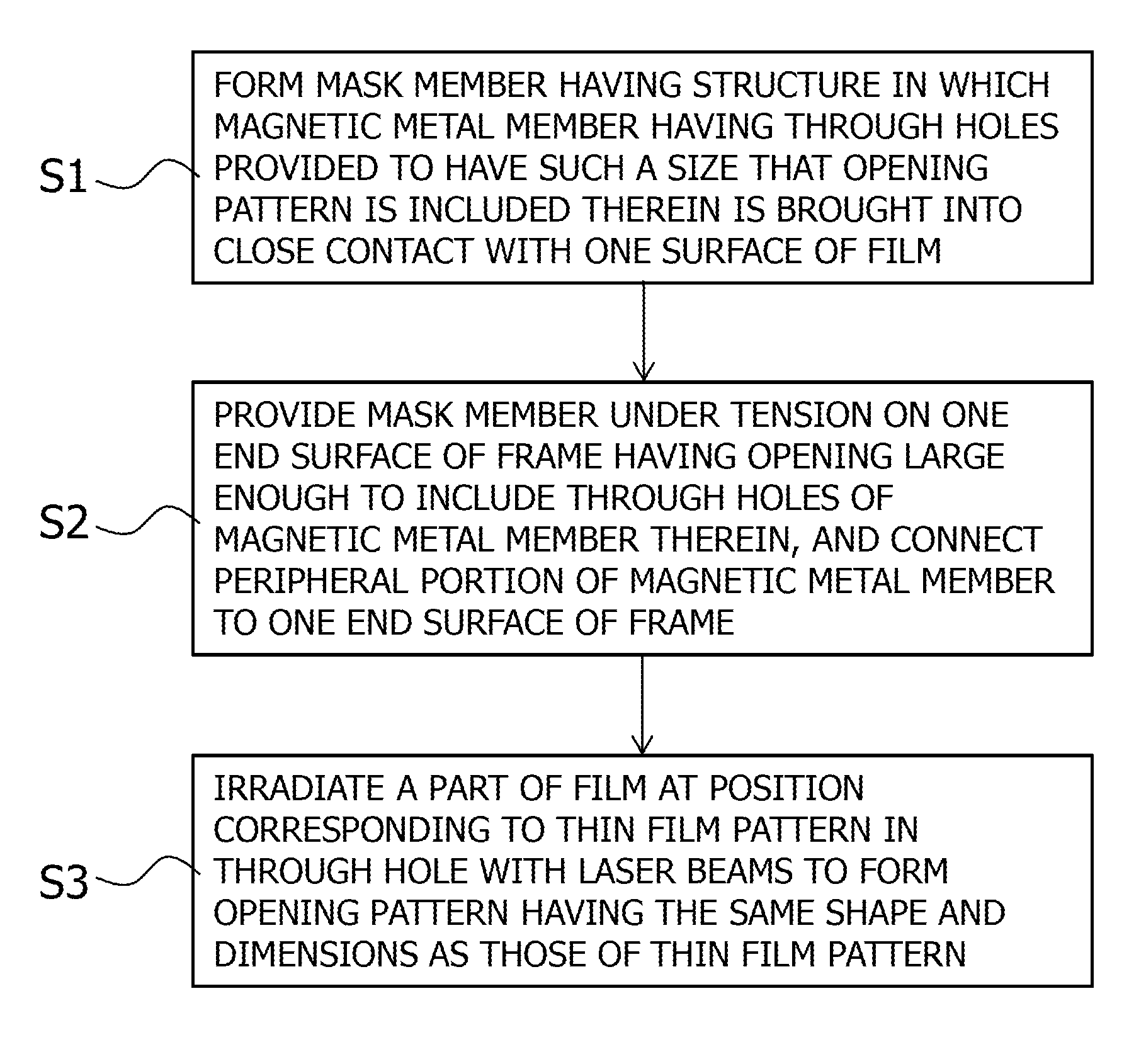
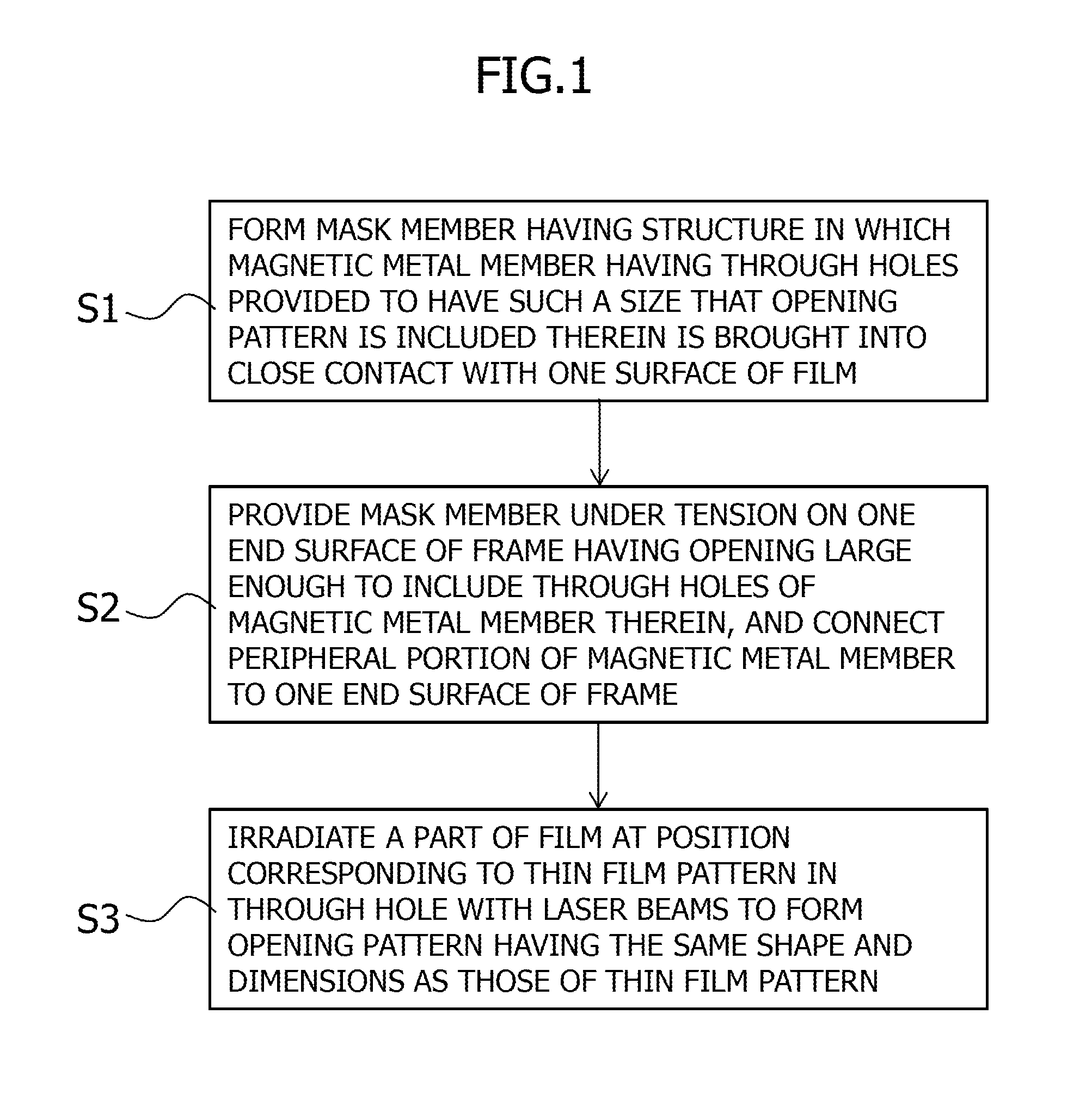
[0022]Hereinafter, an embodiment of the invention will be described in detail with reference to the accompanying drawings. FIG. 1 is a flowchart illustrating a method for producing a deposition mask according to an embodiment of the invention. In this method for producing a deposition mask, an opening pattern is formed at a predetermined position in a resin film by laser processing so as to penetrate therethrough, and Step S1 for forming a mask member, Step S2 for connecting a frame, and Step S3 for forming opening patterns are included.

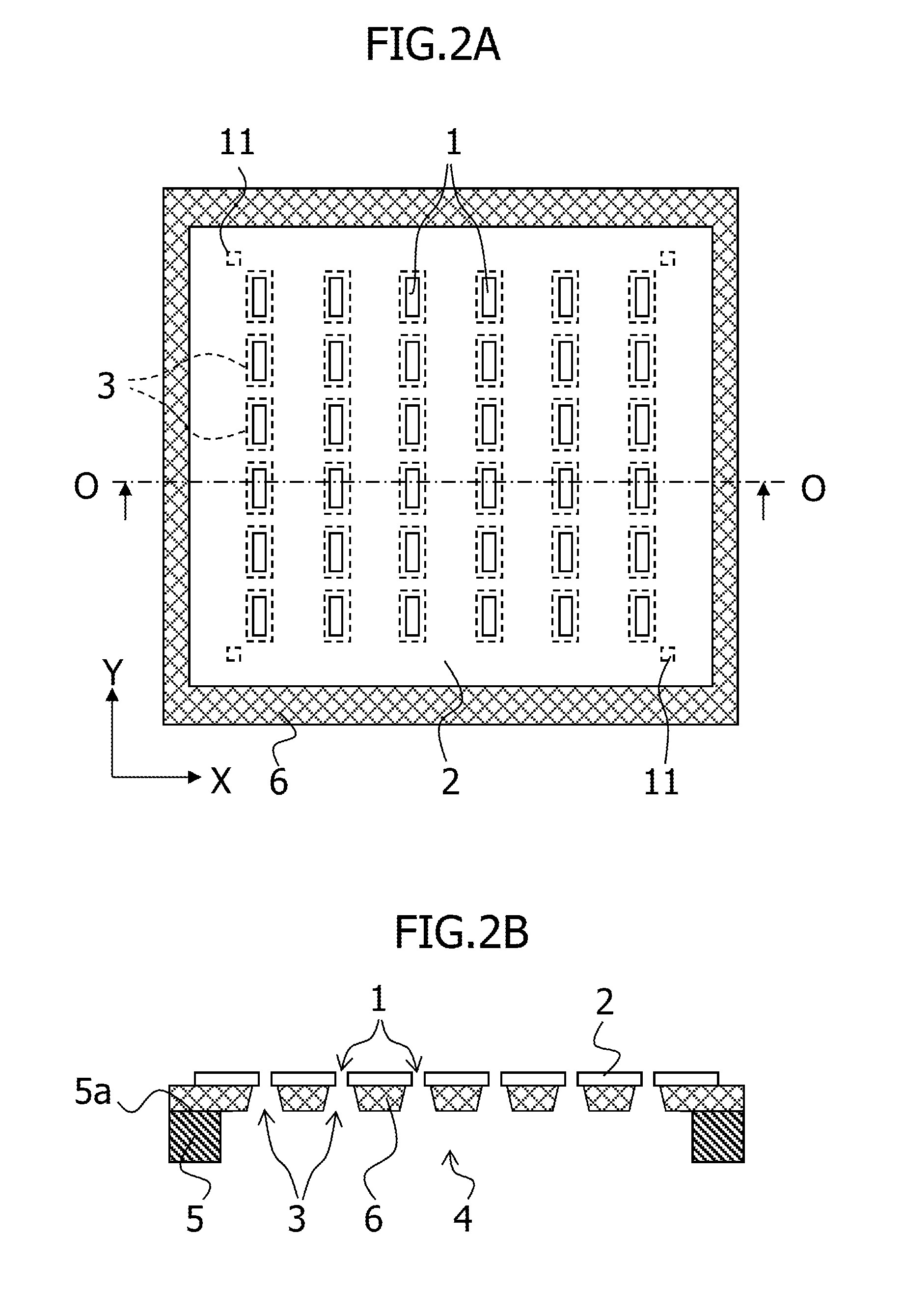
[0023]Here, as an example, what is described is a method for producing a deposition mask having a structure in which, as illustrated in FIG. 2A and 2B, one surface of a resin film having a plurality of opening patterns 1 penetrating therethrough and formed at positions corresponding to a plurality of thin film patterns to be formed, the opening patterns 1 having the same shape and dimensions as those of the thin film pattern is brought into close con...


PUM

PropertyMeasurementUnit
Forceaaaaaaaaaa
Sizeaaaaaaaaaa
Speedaaaaaaaaaa

Abstract

The invention provides a method for producing a deposition mask that includes forming of an opening pattern 1 at a predetermined position in a resin film 2 by laser processing so as to penetrate therethrough. The method including the steps of: forming a meniscus of a liquid film 14 between the resin film 2 and a smooth surface 13b of a reference substrate 13 supporting the resin film 2; and after the resin film 2 and the reference substrate 13 are brought into close contact with an adsorption force generated by Laplace pressure, forming the opening pattern 1 by performing the laser processing. Accordingly, it is possible to increase the speed of the laser processing without generating a burr on an edge portion of the opening pattern.

Description

CROSS-REFERENCE TO RELATED APPLICATIONS[0001]The present application is a continuation of International Application No. PCT / JP2013 / 078162, filed on Oct. 17, 2013, which claims priority from Japanese Patent Application No. 2012-279276, filed on Dec. 21, 2012, the disclosures of which are hereby incorporated herein by reference.BACKGROUND OF THE INVENTION[0002]1. Field of the Invention[0003]The present invention relates to a method for producing a deposition mask, that includes forming of an opening pattern at a predetermined position in a resin film by laser processing so as to penetrate therethrough, and more particularly, relates to a method for producing a deposition mask enabling high-speed laser processing.[0004]2. Description of Related Art[0005]In conventional methods for producing a deposition mask, a first resist pattern having a plurality of openings is formed on a metal plate, an etching process is performed via the openings of the first resist pattern to form a plurality ...

Claims


Application Information

Patent Timeline
IPC IPC(8): B23K26/38B05C21/00B23K26/40
CPCB23K26/381B05C21/005B23K26/4065B23K26/0869C23C14/042B23K26/382B23K2103/42B23K2103/50C23F1/02B23K26/402
Inventor KUDO, SYUJIYANAGAWA, YOSHIKATSUGOTO, TAKAYUKI
Owner V TECH CO LTD
Why Eureka
Try Eureka