The installation of deep foundations in the ground often require numerous steps to be effectively completed, and is very technique dependent.
Foundation elements may be constructed by many methods, with each method having its own associated difficulties and limitations with respect to the assessment of the true profile of the excavation and, consequently, the success with which the concrete / grout has been delivered and the shape of the cured material after
casting.
Until recently, it was one of the few non-
destructive testing techniques which can provide an assessment along the full length of the foundation element The joining of the CHSL tubes at the reinforcement splice levels is difficult and has been an issue of safety for the deep foundation industry with many injuries occurring when the tubes, which are often long and heavy, need to be lifted and connected which can be by
welding or screw connection or just push fit and where arms and fingers need to be inserted within the reinforcement cage during connection and installation of each reinforcing cage which carries the CHSL access tubes.
There are several limitations of the CHSL testing method:1. The zone of material assessment is limited to the path between access tubes;2. The test cannot detect any anomalies outside of the reinforcement cage;3. The access tubes have to be nominally parallel to the
pile or shaft axes;4. The tubes need to be filled with
clean water prior to performing the test.5. The access tubes must be clean internally and fully bonded to the concrete externally.
Any debris,
grease or joint taping may be misinterpreted as an anomaly in the structure;6. The method is not suitable for smaller
pile / shaft diameters where the percentage of the cross section due to the tubes is high;7. Joining of the tubes at each cage splice level is difficult,
time consuming and presents many safety issues;8. Leakage of the tubes due to filling with water when the concrete is wet to assist bonding may result in washing of concrete locally around the joints causing the very anomalies the test can detect;9. No indication of the quality of the concrete at the base is possible;10.
Assessment of concrete quality is limited as
transit time changes of 20% may be expected from minor changes in position of the sensors.11.
This may be deliberate due to
pile construction and / or a consequence of the surrounding soils.4. Poor concrete.
It is not suitable for large
diameter shafts, rectangular sections such as walls or piles that are not of uniform construction such as injection columns or soil mix columns.
Major anomalies and horizontal cracks may be detected but minor anomalies are difficult to detect or define and accurately assess.
The Thermal Integrity Profiling (TIP) technique addresses some of the issues raised above and the methods employed are described in U.S. Pat. No. 6,783,273 and U.S. Pat. No. 8,382,369 but do not allow for detailed profiling without the placement of additional reservation pipework for probe access or the permanent installation and consequent loss of expensive strings of
thermal sensors due to their permanent
embedment in the structure.
1. As described in U.S. Pat. No. 6,783,273, a probe pulled from the bottom of a large
diameter tube (normally a cross hole
logging tube 50 mm or 60 mm OD or larger) to the top of the foundation element (or vice versa) by means of a tripod arrangement at the head of the access tube with a means of locating the sensor in the centre and fitted with a depth
encoder to allow correlation of the temperature measurements with the elevation within the foundation element. The access tubes are normally dry and the probes use thermal imaging techniques requiring a relatively large
diameter tube to be pre-installed in the foundation element before concrete placement. The tube is required to be dry for the
infrared measurements to be possible and, as the act of pulling the
infrared sensor probe in a fluid would produce some turbulence by the probe causing flow of fluid around the sensor, it would affect accurate local temperature measurements of the surrounding concrete / grout. The procedure of measuring the distribution of temperature may be carried out once or several times in the same access tube during the concrete curing process. Several reservation tubes may be installed at different locations parallel to the axis of the foundation element.
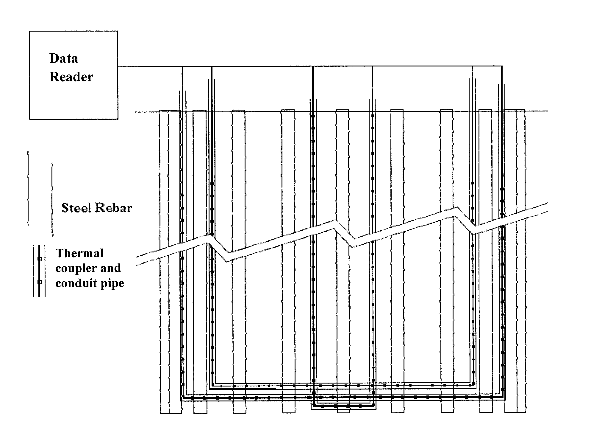
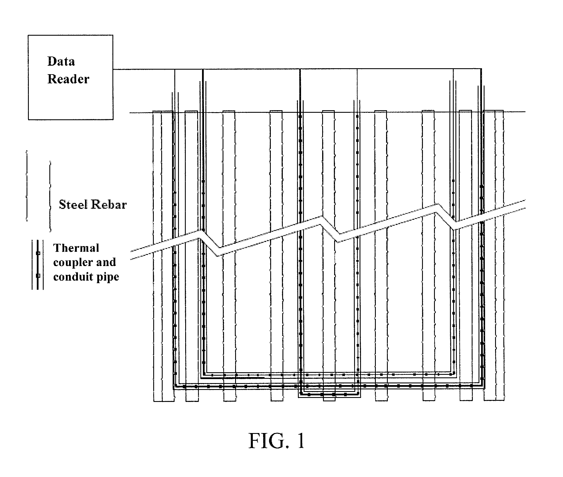
2. As described in U.S. Pat. No. 8,382,369, a fixed permanently embedded thermal string may be used in which a series of individual sensors, such as type K thermocouples may be used and attached to the reinforcement of the foundation element prior to
casting. Alternative thermal strings may be made up in series using MEMS technology, thus minimizing the number of
electrical connection cables required and allowing a plurality of sensors to be deployed that may be read consecutively once the concrete has been cast. The
string length may be manufactured, to correspond to the cage length or standard lengths with suitable electrical connections required at the splicing elevations. Alternatively, they may be continuous and manufactured the full length of the multiple section cage and be tied to outside of the reinforcing cage as it is being inserted into the bore.
Significant variations in the temperature in real time, as a result of changes in the localized concrete and / or grout curing temperature due to heat generated by hydration, are affected by the geometry and density of the surrounding materials and these variations in temperature may be due to anomalies within the concrete and / or grout material.
