
Removable occlusion system for aneurysm neck

a neck aneurysm and occlusion technology, applied in the field of aneurysm neck aneurysm system, can solve the problems of permanent and irreversible occlusion of parent artery, disadvantages of injection of these types of embolic materials, and patient undergoing a great deal of trauma

Inactive Publication Date: 2007-06-12
STRYKER CORP +1
View PDF51 Cites 254 Cited by
  • Summary
  • Abstract
  • Description
  • Claims
  • Application Information

AI Technical Summary

Problems solved by technology

Also, the patient undergoes a great deal of trauma in the area of the aneurysm by virtue of the fact that the surgeon must sever various tissues in order to reach the aneurysm.
The injection of these types of embolic materials suffer from disadvantages, most of which are associated with migration of the embolic material out of the aneurysm into the parent artery.
This can cause permanent and irreversible occlusion of the parent artery.
Further, it is, at times, difficult to gauge exactly how full the sac of the aneurysm is when detachable coils are being injected.
Therefore, there is a risk of overfilling the aneurysm in which case the detachable coils also spill out into the parent artery.
Another disadvantage of detachable coils involves coil compaction over time.
Continued hemodynamic forces from the circulation act to compact the coil mass resulting in a cavity in the aneurysm neck.
Embolic agent migration is also a problem.
This can also lead to irreversible occlusion of-the parent vessel.
Also, in certain cases, it is highly undesirable to occlude the parent vessel even temporarily.
Therefore, this technique is, at times, not available as a treatment option.
In addition, even occluding the parent vessel may not prevent all embolic material migration into the parent vessel.
However, detachable balloons also suffer disadvantages.
For example, detachable balloons, when inflated, typically will not conform to the interior configuration of the aneurysm sac.
Thus, there is an increased risk that the detachable balloon will rupture the sac of the aneurysm.
Further, detachable balloons can rupture and migrate out of the aneurysm.

Method used


Image

  • Removable occlusion system for aneurysm neck
  • Removable occlusion system for aneurysm neck
  • Removable occlusion system for aneurysm neck

Examples


Embodiment Construction

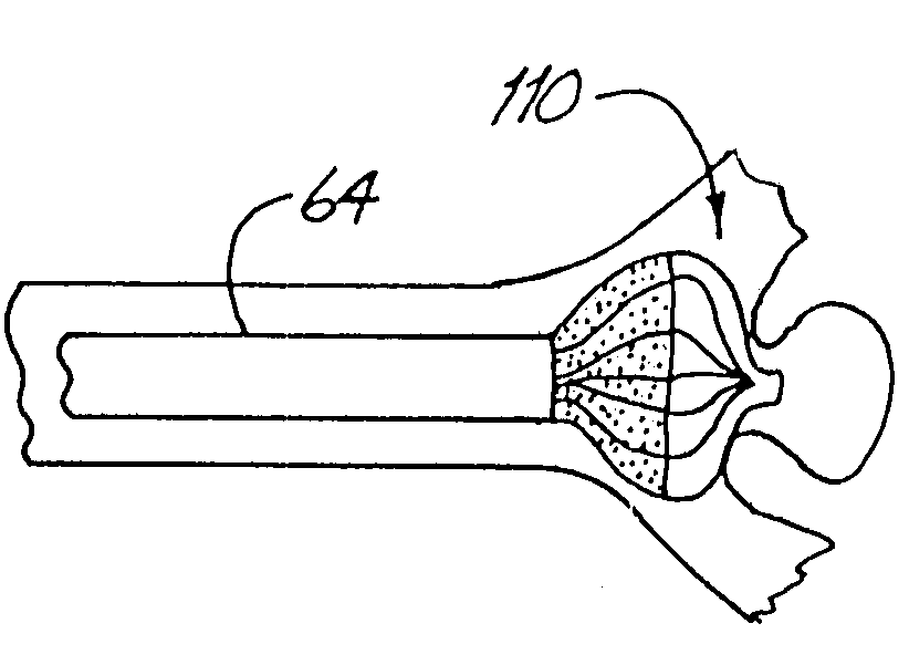
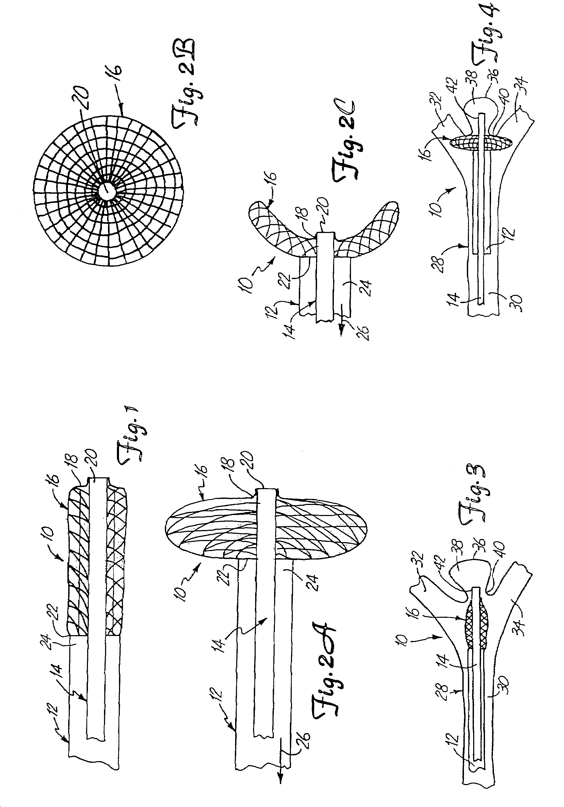
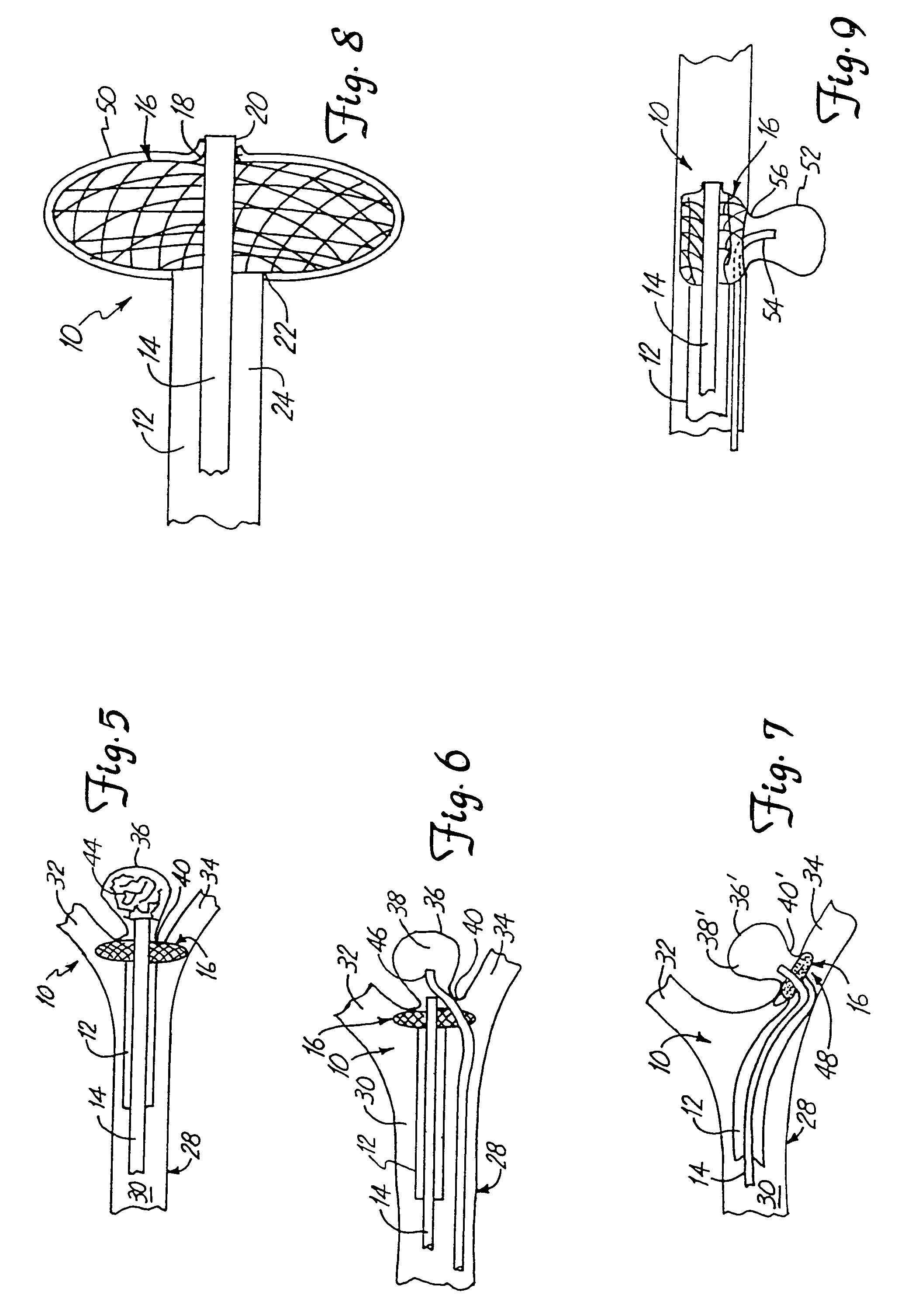
[0023]FIG. 1 is a side view of a portion of a neck occlusion device 10 in accordance with the present invention. Device 10 includes outer tubular member 12, inner tubular member 14, and mesh portion 16. Tubes 12 and 14 are preferably coaxially arranged relative to one another, and are longitudinally slidable relative to one another. Mesh portion 16 is attached, at its distal end 18, to a distal portion 20 of inner tubular member 14. Mesh 16 is attached at its proximal end 22 to a distal portion 24 of outer tubular member 12.

[0024]Mesh portion 16 is preferably formed of braided or woven filaments or fibers which are relatively flexible. Therefore, when tubes 12 and 14 are moved relative to one another, mesh portion 16 is deployed radially outwardly relative to the tubes 12 and 14. This is illustrated by FIG. 2A.

[0025]FIG. 2A shows similar items to those shown in FIG. 1, and they are similarly numbered. However, in FIG. 2A, inner tube 14 has been retracted in the direction indicated b...


PUM


Abstract

A system for treating an aneurysm in a vessel includes a delivery device having a delivery portion suitable for delivery of embolic material. The delivery device is placed in a neck of the aneurysm and an expandable member is placed proximate the neck. The expandable member is expanded to overlie substantially the entire neck. Embolic material is delivered to the aneurysm with a delivery device. The expandable member is held over the neck to inhibit movement of the embolic material out of the aneurysm. Blood is allowed to flow out of the aneurysm, past the neck of the aneurysm, and through the vessel while the expandable member is held over the neck of the aneurysm.

Description

CROSS-REFERENCE TO RELATED APPLICATION[0001]This application is a continuation of U.S. application Ser. No. 09 / 990,978, filed Nov. 20, 2001 and entitled “REMOVABLE OCCLUSION SYSTEM FOR ANEURYSM NECK” now U.S. Pat. No. 6,780,196, which is a divisional application of U.S. application Ser. No. 09 / 301,084, filed Apr. 28, 1999 and entitled “REMOVABLE OCCLUSION SYSTEM FOR ANEURYSM NECK”, which issued as U.S. Pat. No. 6,344,048, which is a divisional of U.S. application Ser. No. 08 / 891,011, filed on Jul. 10, 1997, entitled REMOVABLE OCCLUSION SYSTEM FOR ANEURYSM NECK” which issued as U.S. Pat. No. 5,928,260 on Jul. 27, 1999.BACKGROUND OF THE INVENTION[0002]The present invention deals with a system for treating an aneurysm. More specifically, the present invention deals with a removable occlusion system deployed in the vasculature containing the aneurysm.[0003]Several methods of treating aneurysms have been attempted, with varying degrees of success. For example, open craniotomy is a proced...

Claims


Application Information

Patent Timeline
Patent Type & Authority Patents(United States)
IPC IPC(8): A61M29/00A61B17/00A61B17/12
CPCA61B17/12022A61B17/12036A61B17/1204A61B17/12113A61B17/12172A61B17/12186A61B17/0057A61B19/54A61B2017/00867A61B2017/1205A61B90/39
Inventor CHIN, YEMMCCRORY, JENNIFERTREMAGLIO, JR., ANTHONY R.HUDSON, RICHARD D.
Owner STRYKER CORP
Learn More