
Carbon nanotube having high specific surface area and method for manufacturing same

a carbon nanotube and specific surface technology, applied in the field of carbon nanotubes, can solve the problems of limited industrial application and use of carbon nanotubes, high arc production costs or expensive laser equipment, and carbon nanotube diameter and length limitation, etc., to achieve high specific surface area, improve physical properties, and high dispersibility and miscibility.

Active Publication Date: 2015-10-01
LG CHEM LTD
View PDF5 Cites 17 Cited by
  • Summary
  • Abstract
  • Description
  • Claims
  • Application Information

AI Technical Summary

Benefits of technology

This patent describes a new type of carbon nanotube that has a large surface area and is easy to mix with other materials. These carbon nanotubes can be used to create composite materials with better physical properties, making them useful in a variety of applications such as energy materials, function composites, pharmaceuticals, batteries, semiconductors, and display devices. The method described in this patent allows for the production of these carbon nanotubes in high yield.

Problems solved by technology

However, carbon nanotubes have a limitation in directly controlling the diameter and length to industrially applicable dimensions for practical use owing to their primary structure.
Accordingly, the industrial application and use of carbon nanotubes are limited despite their excellent physical properties.
However, arc discharge and laser ablation are not appropriate for mass production of carbon nanotubes and require high arc production costs or expensive laser equipment.
Chemical vapor deposition using a vapor dispersion catalyst has the problems of a very low synthesis rate and too small a size of final CNT particles.
Chemical vapor deposition using a substrate-supported catalyst suffers from very low efficiency in the utilization of a reactor space, thus being inappropriate for mass production of CNTs.

Method used


Image

  • Carbon nanotube having high specific surface area and method for manufacturing same
  • Carbon nanotube having high specific surface area and method for manufacturing same
  • Carbon nanotube having high specific surface area and method for manufacturing same

Examples


example 1

A. Preparation of Aqueous Solution of Graphitization Metal Catalyst Precursor

[0098]A Co-V metal catalyst as a graphitization catalyst was prepared by the following procedure.

[0099]Citric acid was added to a solution of NH4VO3 as a V precursor in 20 ml water in flask A, and then Co(NO3)2.H2O as a Co precursor was added thereto to prepare an aqueous metal solution. The V precursor and the Co precursor were added in such amounts that the molar ratio of Co:V was 10:1. The aqueous metal solution was observed to be clear and free of precipitates.

B. Preparation of Support

[0100]Aluminum trihydroxide (Al(OH)3) as an aluminum-based support was calcined at 400° C. for 4 h to obtain ATH400. 20 g of ATH400 was placed in flask B. XRD analysis revealed the presence of 40 wt % of AlO(OH) in the calcined support.

C. Preparation of Supported Catalyst

[0101]40 g of the solution in flask A was added to flask B such that the numbers of moles of Co and V were 30 moles and 3 moles, respectively, when the nu...

example 2

[0109]Bundle type CNTs were produced in the same manner as in Example 1, except that ATH300 was obtained by calcining aluminum trihydroxide at 300° C. instead of 400° C.

[0110]The CNTs were found to have the following physical properties:

[0111]Yield=9.68 times

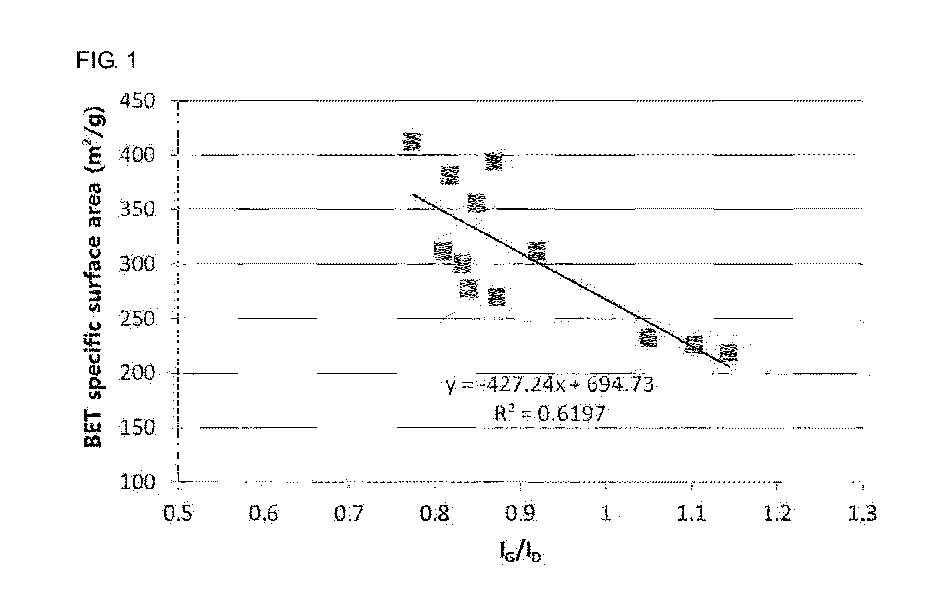
[0112]BET specific surface area=412 m2 / g

[0113]IG / ID=0.7738±0.0407

example 3

[0114]Bundle type CNTs were produced in the same manner as in Example 2, except that the temperature of the reactor was changed from 670° C. to 690° C.

[0115]The CNTs were found to have the following physical properties:

[0116]Yield=9.25 times

[0117]BET specific surface area=394 m2 / g

[0118]IG / ID=0.8690±0.0604


PUM

PropertyMeasurementUnit
Temperatureaaaaaaaaaa

Abstract

Provided is a method for preparing a supported catalyst that enables the production of carbon nanotubes having a large specific surface area in high yield. Carbon nanotubes produced using the supported catalyst are also provided. The carbon nanotubes are suitable for use in various applications due to their large specific surface area and high yield.

Description

BACKGROUND OF THE INVENTION[0001]1. Field of the Invention[0002]The present invention relates to a method for preparing a supported catalyst, and more particularly to carbon nanotubes having a large specific surface area and a method for producing the carbon nanotubes.[0003]2. Description of the Related Art[0004]Carbon nanostructures (CNSs) refer collectively to nano-sized carbon structures having various shapes, such as nanotubes, nanohairs, fullerenes, nanocones, nanohorns, and nanorods. Carbon nanostructures can be widely utilized in a variety of technological applications because they possess excellent characteristics.[0005]Carbon nanotubes (CNTs) are tubular materials consisting of carbon atoms arranged in a hexagonal pattern and have a diameter of approximately 1 to 100 nm. Carbon nanotubes exhibit insulating, conducting or semiconducting properties originated from their inherent chirality. Carbon nanotubes have a structure in which carbon atoms are strongly covalently bonded ...

Claims


Application Information

Patent Timeline
IPC IPC(8): C01B31/02B01J23/847B01J23/881B01J21/02B01J23/882
CPCC01B31/0233B01J21/02C01B2202/32B01J23/881B01J23/8472B01J23/882B01J21/185B01J23/8906B01J23/8913B82Y30/00B82Y40/00B01J37/08B01J37/10B01J37/0203B01J37/0207C01B32/162C01B2202/22Y10T428/2982Y10T428/2918B01J35/30B01J35/33B01J35/23B01J35/40C01B32/158B01J37/084C01B32/16
Inventor KIM, SUNGJINSON, SEUNGYONGWOO, JIHEELEE, DONGCHULKANG, KYUNGYEON
Owner LG CHEM LTD
Learn More