
Laser processing device having function for monitoring propagation of laser beam

a laser beam and processing device technology, applied in laser beam welding apparatus, instruments, manufacturing tools, etc., can solve the problems of contaminated reflecting mirrors, affecting laser processing, and affecting the accuracy of laser beam expansion and misalignment detection, etc., to achieve the effect of simple structure and accurate detection of expansion and misalignment of laser beams

Inactive Publication Date: 2015-09-24
FANUC LTD
View PDF4 Cites 8 Cited by
  • Summary
  • Abstract
  • Description
  • Claims
  • Application Information

AI Technical Summary

Benefits of technology

The present invention is aimed at providing a laser processing device that has a simple structure and can detect the expansion and misalignment of a laser beam accurately.

Problems solved by technology

In the prior art, when a paint or thinner is used in a factory where the laser processing device is located, impurity gas may enter the beam path so that (a diameter of) the laser beam is expanded, whereby the laser processing may be disadvantageously affected.
Further, a beam axis may be shifted or misaligned due to vibration of peripheral equipment.
Further, when the aperture member is irradiated with a laser beam having significant power, heat deformation of the aperture member and / or evaporation of a coating of the aperture member may occur, whereby the reflecting mirror may be contaminated.
Therefore, when the laser processing is carried out at relatively low output power, the sensor may not detect the laser beam attenuated by the above means.
Further, when the reflected light is used (i.e., the laser beam is indirectly monitored), the response of the sensor may be delayed.
(a3) Since a part of the beam path is narrowed by the aperture, purge gas cannot smoothly flow within the beam path when purging, whereby the purge gas easily stagnates in the beam path.
(b3) Fine particles such as dust may affect the propagation of the laser beam, whereas a normal gas sensor cannot detect particles.
In addition, in a method (c) for dispersing a laser beam and monitoring it by means of a profiler, an apparatus therefor is relatively large, complicated and expensive.
Therefore, it is difficult to apply method (c) to a mass-production system.
However, in a normal state, since the laser beam transmits through the peripheral portion and the transmitted laser beam is received by the sensor, the expansion of the laser beam (or the laser diameter) relative to the normal state cannot be detected.
In addition, it may be difficult to manufacture the partial transmitting mirror having the circular center total reflecting portion and the peripheral portion thereof.
Further, when an outer peripheral portion of the partial transmitting mirror is irradiated with the laser beam, it is difficult to estimate reflection, absorption and subsequent diffraction of the laser beam.

Method used


Image

  • Laser processing device having function for monitoring propagation of laser beam
  • Laser processing device having function for monitoring propagation of laser beam
  • Laser processing device having function for monitoring propagation of laser beam

Examples


Embodiment Construction

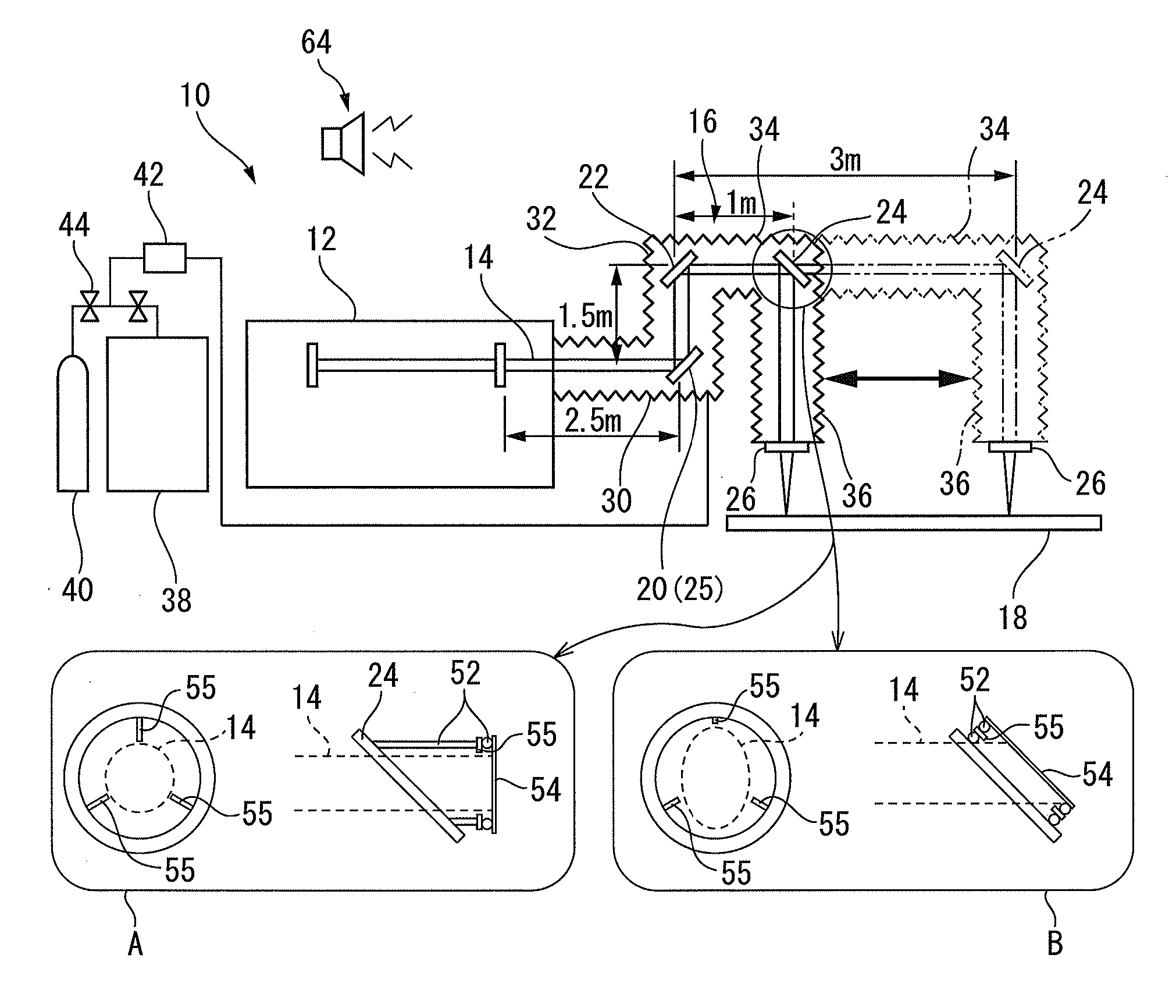
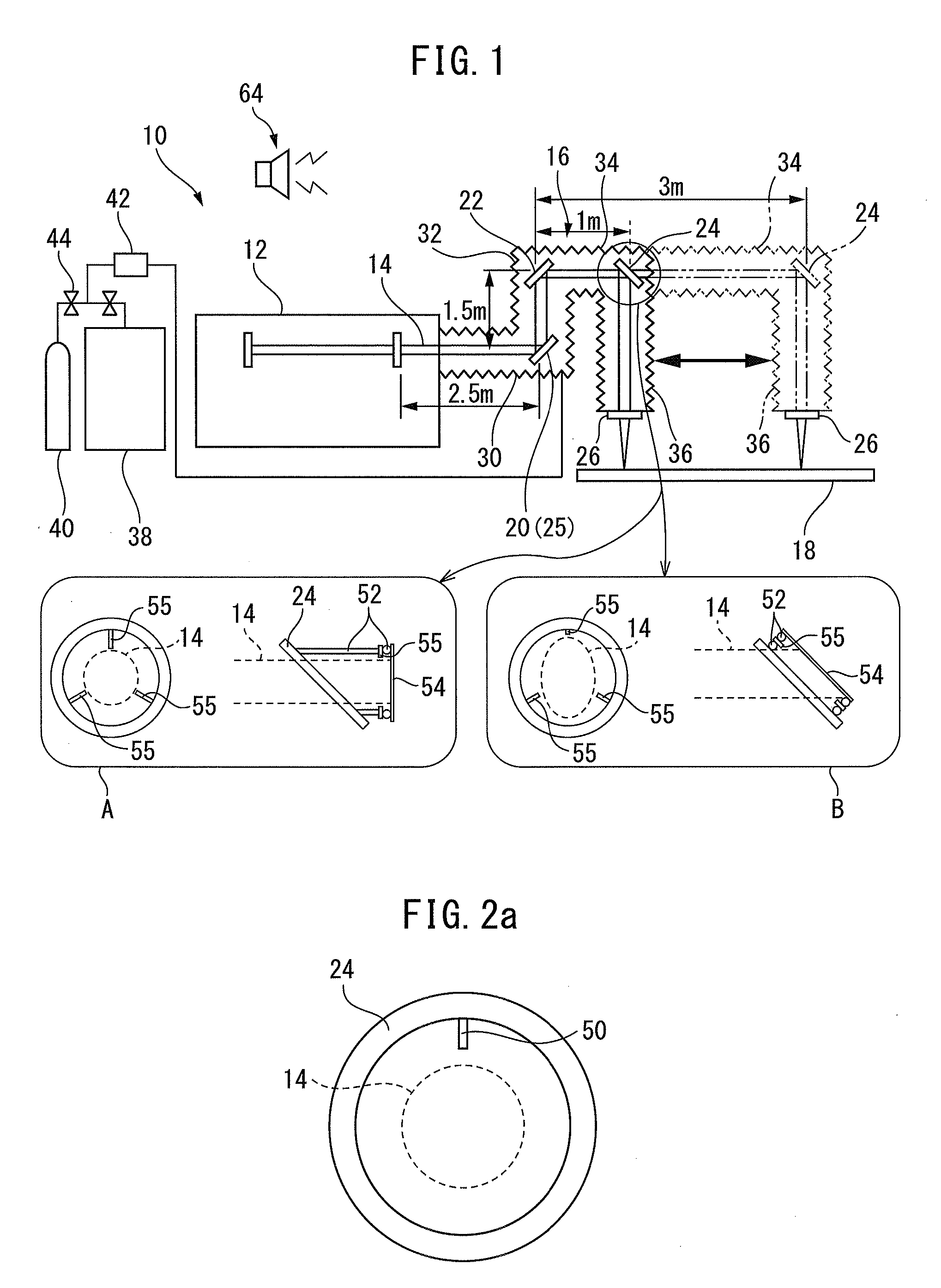
[0055]FIG. 1 shows a schematic configuration of a laser processing device according to a preferred embodiment of the present invention. Laser processing device 10 includes a gas laser oscillator 12, a laser medium of which is carbon dioxide, etc.; a beam path (or a laser transmission path) 16 through which a laser beam 14 output from laser oscillator 12 passes; and at least one reflecting mirror positioned in beam path 16, wherein laser beam 14 propagates within beam path 16 and is introduced to a workpiece 18 to be processed. In the illustrated embodiment, laser beam 14 irradiated from laser oscillator 12 is totally reflected by a first reflecting mirror 20 and a second reflecting mirror 22, is reflected by a movable half mirror (or a partially transmitting mirror) 24, and then transmits through a movable process lens 26 so that a predetermined processing is carried out with respect to workpiece 18. In addition, dimensions indicated in FIG. 1 are merely examples, and the present in...


PUM

PropertyMeasurementUnit
reflection angleaaaaaaaaaa
diameteraaaaaaaaaa
diameteraaaaaaaaaa

Abstract

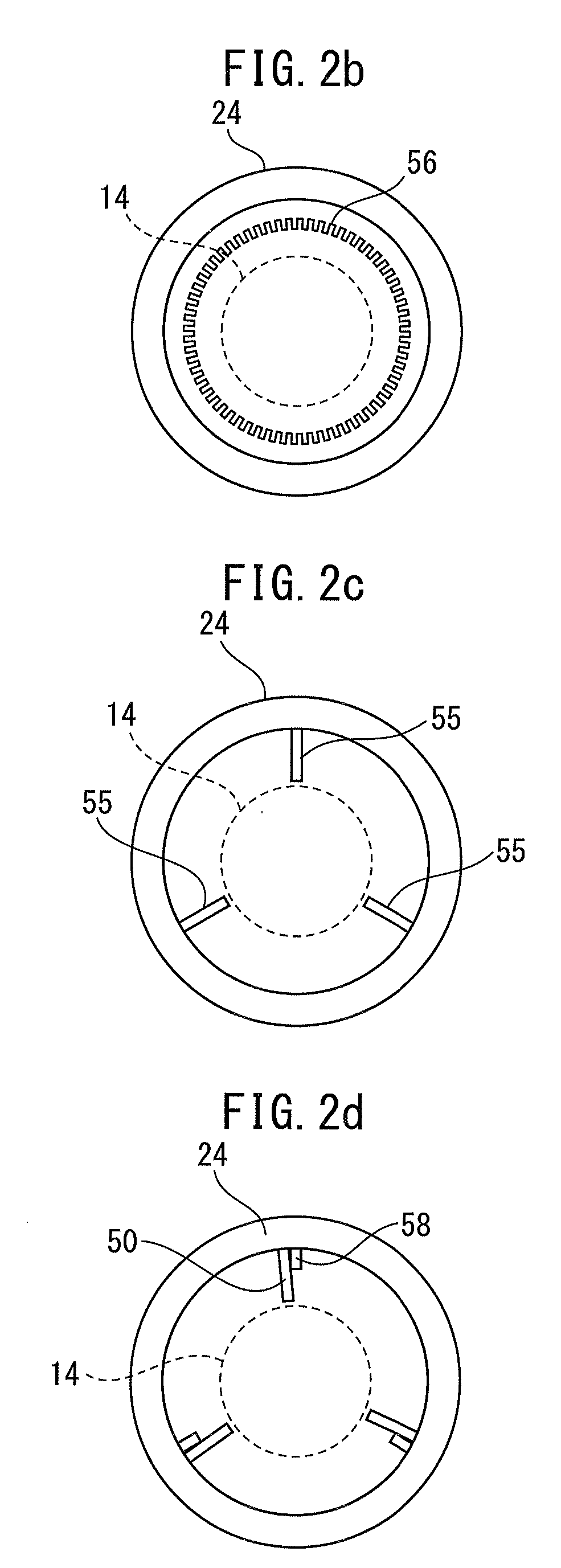
A laser processing device having a simple structure and a means for accurately detecting expansion and misalignment of a laser beam. A sensor, which receives the laser beam after transmitting through a half mirror, is arranged on a back surface of the half mirror opposed to a front surface which reflects the laser beam. The sensor is positioned via a heat insulating material between the back surface of the half mirror and a shield plate for shielding or absorbing the laser beam after transmitting through the half mirror, so that the sensor is thermally-independent from the other components. The sensor is positioned so that the sensor does not receive the laser beam after transmitting through the half mirror in the normal state, and so that the sensor directly receives the laser beam after transmitting through the half mirror when the laser beam is expanded or misaligned.

Description

BACKGROUND OF THE INVENTION[0001]1. Field of the Invention[0002]The present invention relates to a laser processing device having a function for monitoring propagation of a laser beam.[0003]2. Description of the Related Art[0004]In a laser processing device having a gas laser oscillator, a laser beam which is output from the laser oscillator propagates through the atmosphere and is introduced to a processing point via one or more reflecting mirror. Normally, in order to introduce the laser beam to the processing point, a beam path enclosed by a bellows or a duct is purged by using clean gas.[0005]The bellows for constituting the beam path is expanded or contracted when laser processing, and therefore outside air may enter the beam path from a seam of the bellows or a gap between an end of the bellows and a packing arranged at the seam. In the prior art, when a paint or thinner is used in a factory where the laser processing device is located, impurity gas may enter the beam path so ...

Claims


Application Information

Patent Timeline
Patent Type & Authority Applications(United States)
IPC IPC(8): G01B21/24
CPCG01B21/24B23K26/032B23K26/0643B23K26/14B23K26/043B23K26/035
Inventor IZUMI, TAKASHI
Owner FANUC LTD
Learn More