
Eye contact lens insertion and removal apparatus

a contact lens and eye contact technology, applied in the field of eye contact lens insertion and removal apparatus, can solve the problems of difficult and quite stressful process for some people, difficult to judge distances when using such devices close to the eye, and form a strong contact with the eye surfa

Active Publication Date: 2015-09-24
HERSHOFF CRAIG L
View PDF10 Cites 8 Cited by
  • Summary
  • Abstract
  • Description
  • Claims
  • Application Information

AI Technical Summary

Benefits of technology

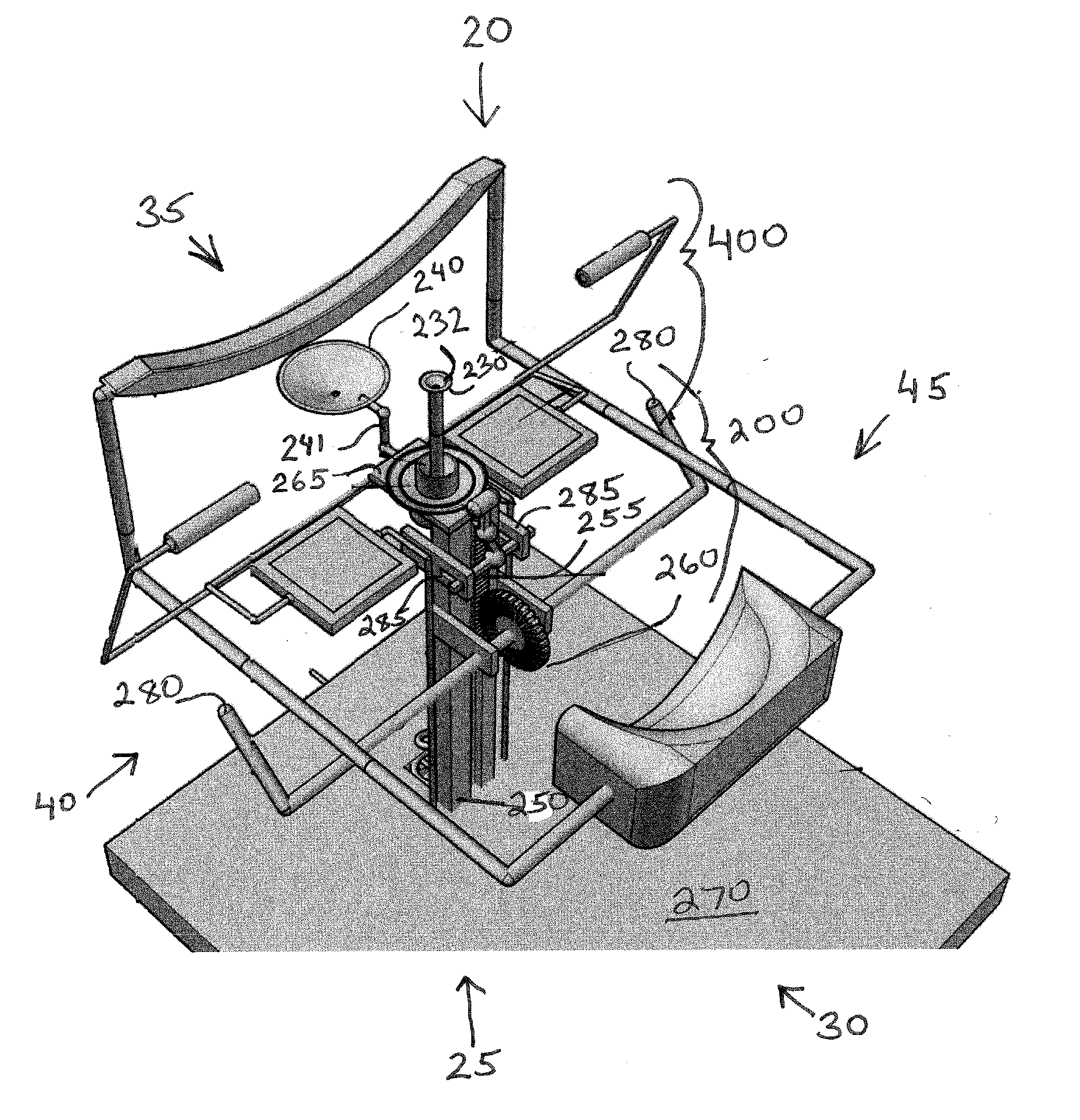
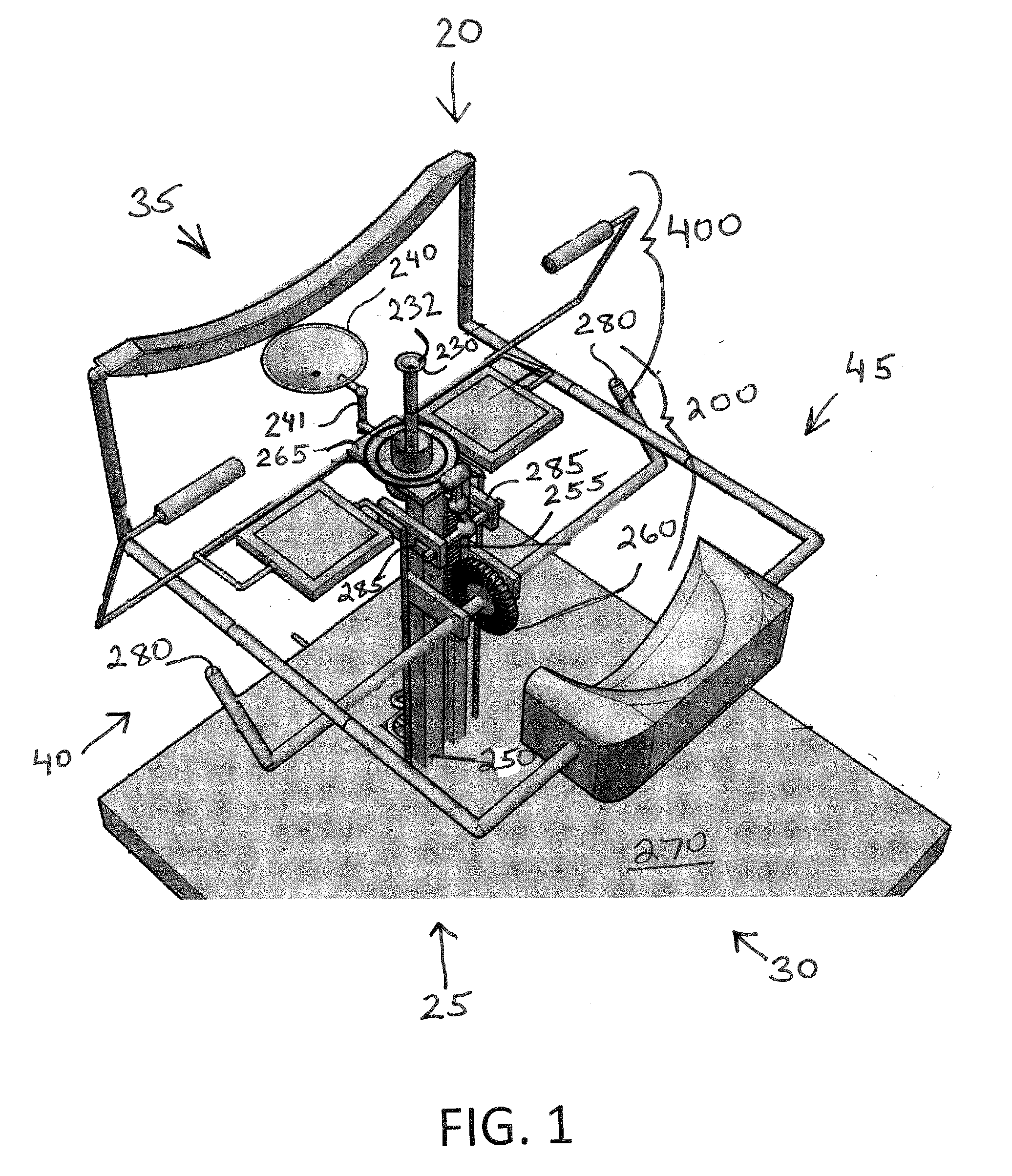
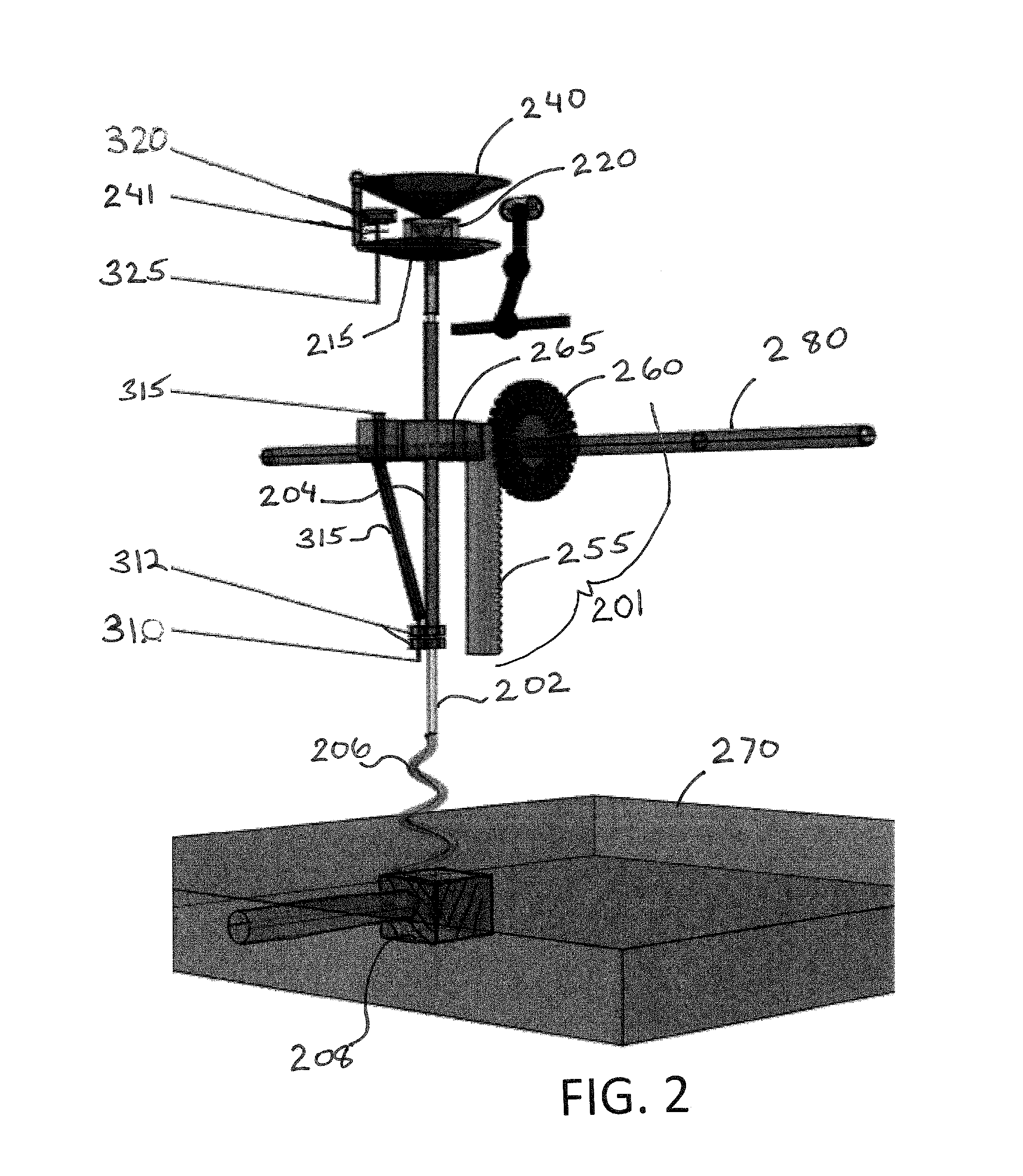
The invention is a device and method for safely and comfortably inserting and removing contact lenses. It uses a lens conveyor system that is controlled by the user with a handle, and a display system to provide a real-time visual image of the process. The lens conveyor system includes a rod with a lens manipulator and a storing and cleaning system for contact lenses. The display system uses strategically placed viewing mechanisms to create an optical illusion and allows the user to watch the lens manipulator approaching the eye from a sideways direction, giving them a sense of safety and control. The embodiments are portable, easy to manipulate, and provide complete control over the entire process, making them suitable for automation. The system is non-electrical and can be sterilized using various methods without adversely affecting the lenses or user.

Problems solved by technology

This process can be difficult and quite stressful for some people to perform.
It can be difficult, however, to judge distances when using such devices close to the eye.
However, if the contact is not immediately released upon adhering to the eye, the suction force can cause painful contact with the cornea or sclera during installation and may even remove the contact instead of leaving it in place.
It is also not uncommon for contacts to form a strong contact with the eye surface, particularly when too dry or when worn for protracted periods.
If the suction of the device is too strong, it can damage the eye while the user is trying to remove a too-strongly adhered contact.
Another issue with contacts is the transmission of dirt, microorganisms, and other undesirable products to the eye.
During transfer the contact can be dropped or dirtied, the fluid necessary for comfortable insertion can leak or drip out of the contact, or the contact can be torn, chipped, or otherwise damaged.

Method used


Image

  • Eye contact lens insertion and removal apparatus
  • Eye contact lens insertion and removal apparatus
  • Eye contact lens insertion and removal apparatus

Examples


first embodiment

[0112]In a first embodiment, a mirror system 410 is utilized for the display system to align the eye with the lens manipulator, as well as to create a overlaid image illusion or ultra-parallax image. With this embodiment, the viewing mechanism 405 is two or more mirrors that can be aligned to provide a line-of-sight 412 that allows the viewing or second eye of a user to see the action of the lens manipulator on the opposite or first eye. FIGS. 19, 20, and 21 illustrate one embodiment utilizing multiple mirrors to align the eye with the lens manipulator, where at least one of the mirrors is the viewing mechanism seen by the second eye. The type of mirrors utilized with this embodiment can be flat or can have a concavity or other shape that is conducive to reflecting the images therein.

[0113]FIG. 19 shows an embodiment that uses a series of concave mirrors 414 to direct an image to the left eye side of the lens manipulator 230. The line-of-sight 412 between each pair of mirrors can be...

second embodiment

[0115]In a second embodiment, a digital imagery system 420 is utilized to provide the second image, which can be mentally combined with the first image, so that the dual images are perceived as overlaid independent images. This embodiment utilizes at least one, optionally two, viewing mechanisms, which can be electronic display screens 430 that are operably connected to at least one, optionally two, video cameras 425. For the following description, reference will be made to FIGS. 8, 10, 12, 14, and 16.

[0116]With the electronic imagery system 420, a motion-capture apparatus 425 can be directed towards about the side of the face of a user engaged with a CLIARA, so as with the mirror system, to provide a view, such as an orthogonal or other ultra-parallax view, to the line-of-vision of the second eye viewing the image. Motion-capture apparatuses are well-known to those with skill in the art and can include, but are not limited to, video cameras, cell phone cameras, single image cameras...


PUM


Abstract

Contact lenses are a commonly used medical device that many users find difficult to insert and remove from the eyes. A contact lens insertion and removal apparatus of the subject invention utilizes a lens manipulator that can be controlled by a user to insert a contact lens into the eye or remove it from the eye. Further embodiments include a display system that provides a user with dual images of the lens manipulator such that the user sees an optical illusion of the lens manipulator from a side view. This provides the user with an increased sense of control and safety when inserting or removing contact lenses. Additional embodiments can include a hands-free contact lens cleaning and storage system.

Description

CROSS-REFERENCE TO RELATED APPLICATION[0001]This application claims the benefit of U.S. Provisional Application Ser. No. 61 / 955,409, filed Mar. 19, 2014, the disclosure of which is hereby incorporated by reference in its entirety, including all figures, tables and drawings.BACKGROUND OF INVENTION[0002]Contact lenses for the eye, commonly referred to as just “contacts,” are a convenient and comfortable way of improving vision. They can eliminate the need for glasses and are particularly advantageous when other ocular devices are used, such as binoculars, diving masks, microscopes, sunglasses, protective eyewear, or other similar types of devices that would be difficult or impossible to use while wearing regular eye glasses. Certain medical conditions can also necessitate the wearing of contact lenses. Cataract surgery where an artificial lens cannot be implanted in the eye may require a patient to wear contacts. Contacts may also be required to treat certain types eye diseases, such ...

Claims


Application Information

Patent Timeline
IPC IPC(8): A61F9/00
CPCA61F2009/0035A61F9/0061
Inventor HERSHOFF, CRAIG L.
Owner HERSHOFF CRAIG L
Learn More