Dental vibration application method and dental vibration application device
a technology of dental vibration and application method, which is applied in the field of dental vibration application method and dental vibration applicator, can solve the problems of imposing a large burden on patients, and achieve the effect of effective range of vibration characteristics, and shortening the treatment period
- Summary
- Abstract
- Description
- Claims
- Application Information
AI Technical Summary
Benefits of technology
Problems solved by technology
Method used
Image
Examples
first embodiment
[0083]Verification of vibrational stimulation characteristics by the present inventors are described in the context of the first embodiment. Various technologies for resolving the aforementioned problems become clear from the following verification.
[0084]The present inventors used the following method to verify vibrational stimulation characteristics, from which the aforementioned effects of shortening an orthodontic treatment period are obtained.
[0085]Male Wistar rats age 22 weeks or older and male beagle dogs age 10 months or older were used to verify the vibrational stimulation characteristics. Schematic views of experimental systems are shown in FIGS. 3A and 3B. FIG. 3A is a schematic view of an experimental system using the rats whereas FIG. 3B is a schematic view of another experimental system using the beagle dogs.
[0086]In the experiment using the rats, the present inventors fabricated a device including an orthodontic wire 21 and placed the device in all the rats so that the...
second embodiment
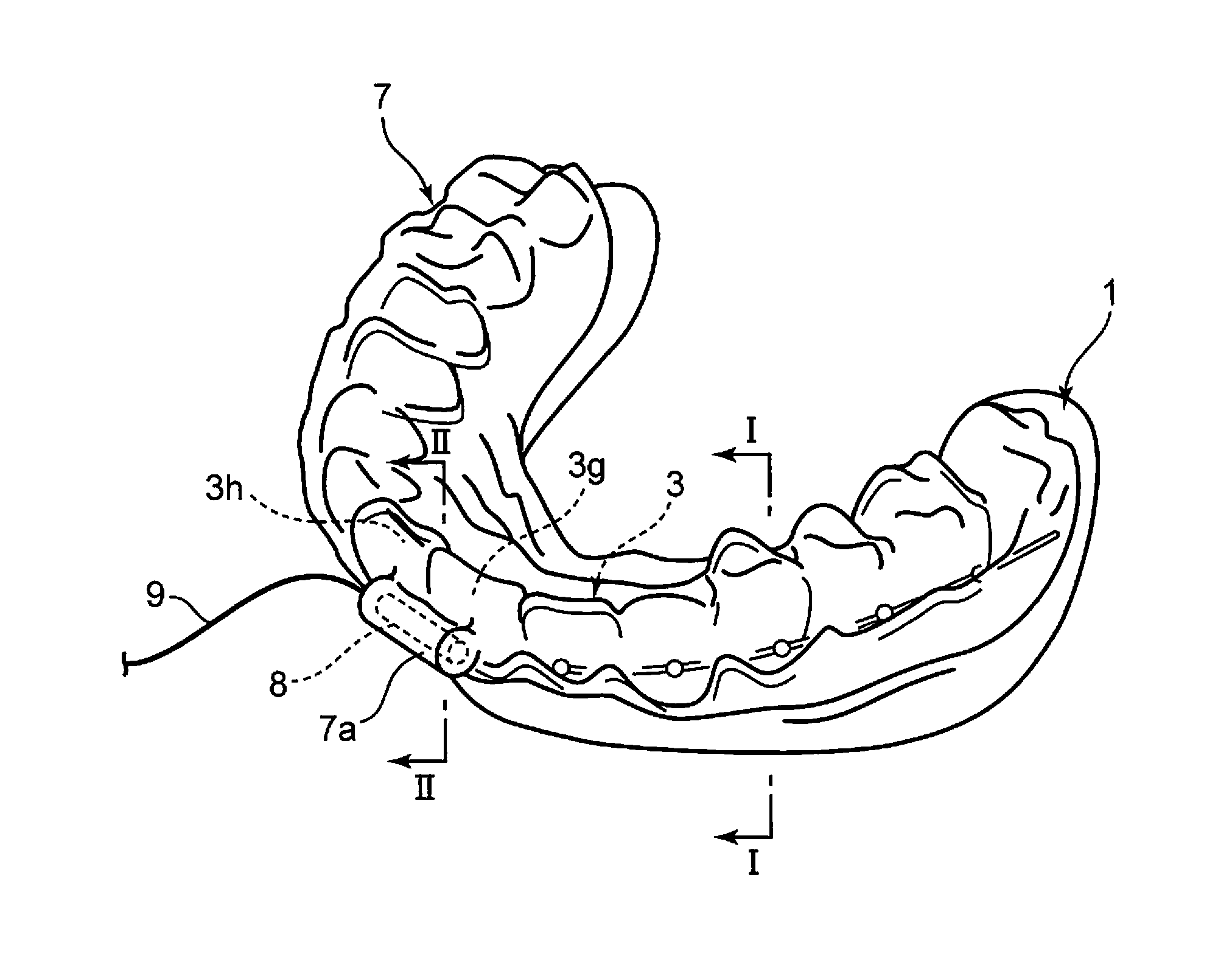
[0107]A device used for shortening an orthodontic treatment period is described in the context of the second embodiment, the device including a vibration generator. The device applies vibration generated by the generator to the teeth or alveolar mucosa of a user.
[0108]The device used for shortening an orthodontic treatment period according to the present embodiment includes a vibration generator, a device (power supply) configured to supply power for the vibration generator, a controller, and a contacting instrument for transmitting the generated vibration.
[0109]FIG. 11 is a perspective view of the mandibular dentition, to which an orthodontic appliance is attached. As shown in FIG. 11, each bracket 4 is fixed to the buccal surface of each of the teeth 3b to 3m of the dentition 3 (a to n) among the dentition and gingival tissue 1. A continuous wire 5 is engaged into each bracket 4. The dentition and occlusion may be treated with the orthodontic appliance by a continuous force applie...
third embodiment
[0119]The use of a mouthpiece described in the context of the second results in easy transmission of vibration to the teeth. However, it may be desired in orthodontic treatment to selectively transmit vibration to a specific tooth. Techniques which allow selective vibration transmission to a specific tooth are described in the third embodiment.
[0120]FIGS. 13A to 13D show an embodiment of a probe-type device which applies vibration to the dentition 3 when a user contacts the device with a tooth.
[0121]FIG. 13A is a schematic perspective view of a vibration generating probe 11. The vibration generating probe 11 includes a rod-shaped body 110 and an arm 111 which extends from an end surface of the body 110. A vibration generator (not shown) configured to generate vibration is stored in the body 110. The arm 111 includes a proximal end 112 connected to the body 110 and a ball-shaped probe head 11a. The probe head 11a is formed on the opposite side of the proximal end 112. Vibration gener...
PUM
 Abstract
Description
Claims
Application Information
 - R&D
- Intellectual Property
- Life Sciences
- Materials
- Tech Scout
- Unparalleled Data Quality
- Higher Quality Content
- 60% Fewer Hallucinations
Browse by: Latest US Patents, China's latest patents, Technical Efficacy Thesaurus, Application Domain, Technology Topic, Popular Technical Reports.
© 2025 PatSnap. All rights reserved.Legal|Privacy policy|Modern Slavery Act Transparency Statement|Sitemap|About US| Contact US: help@patsnap.com


