
Hysteretic buck dc-dc converter

a converter and buck technology, applied in the direction of dc-dc conversion, power conversion systems, instruments, etc., can solve the problems of reducing the accuracy of output signals, affecting the accuracy of buck regulators, and low esr capacitors not generating enough output ripple for feedback control

Inactive Publication Date: 2015-09-17
MICREL
View PDF9 Cites 31 Cited by
  • Summary
  • Abstract
  • Description
  • Claims
  • Application Information

AI Technical Summary

Benefits of technology

The patent text describes a type of power supply called a buck switching regulator, which is used to convert an input voltage to a desired output voltage. The regulator includes a pair of power switches that are turned on and off to regulate the output voltage. The regulator is controlled by a feedback control circuit to maintain a constant output voltage. The technical effect of the invention is to provide a more efficient and precise method for regulating the output voltage of a power supply, which can be important for the operation of integrated circuits.

Problems solved by technology

Recently, low ESR capacitors are preferred to realize improved efficiency in switching regulators but the low ESR capacitors do not generate enough output ripple for feedback control.
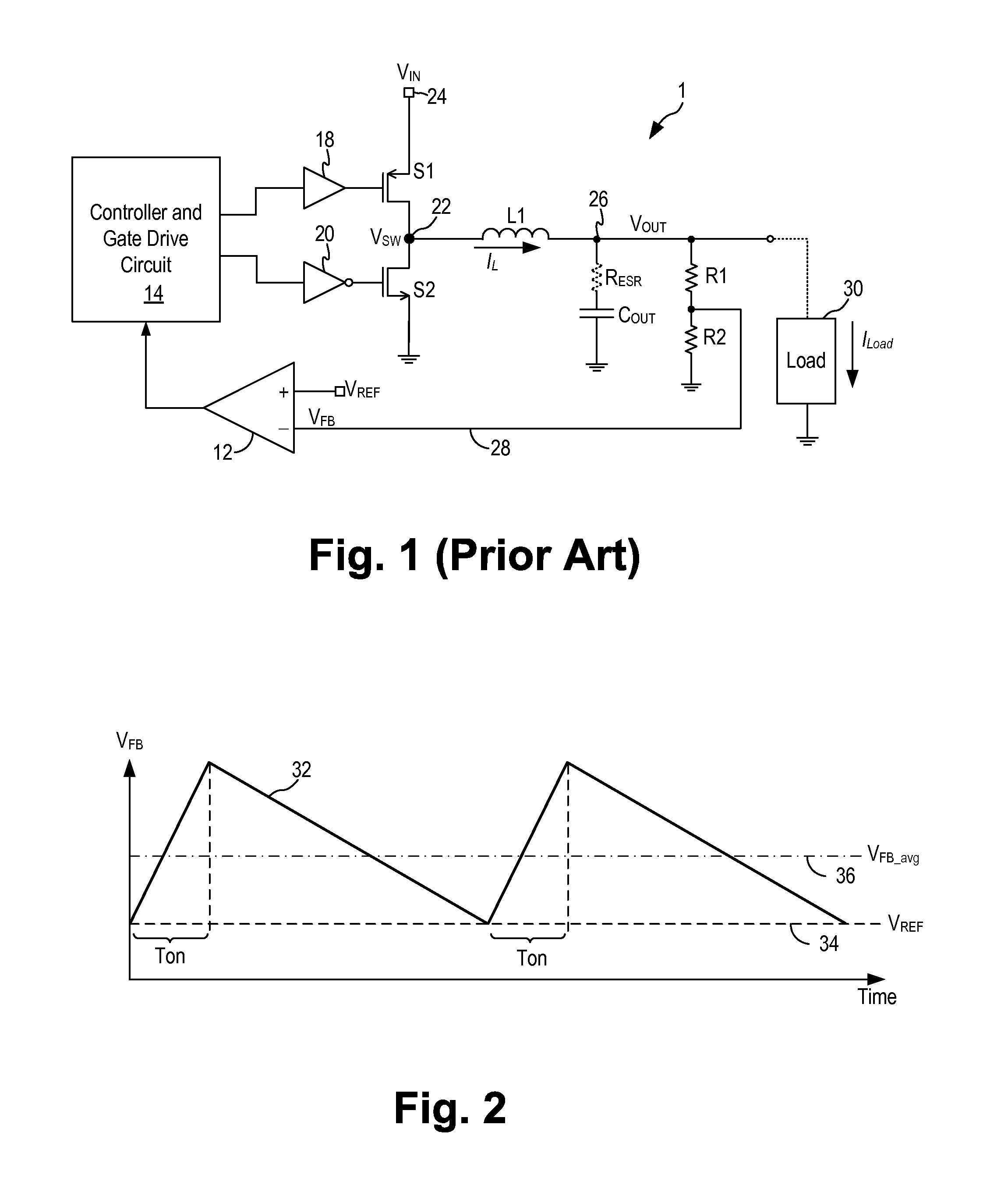
For voltage regulators using ripple-mode control, while the output ripple is useful in output voltage regulation, it is undesirable because the output ripple introduces an offset to the output voltage, reducing the output signal accuracy.
As a result, output voltage VOUT has a DC offset voltage component which affects the accuracy of the buck regulator.
For example, the offset at the feedback voltage may be about 10 mV but the offset is gained up through the control circuit and the power switches, due to the presence of the resistor divider (R1 / R2), so that the output voltage may experience an offset voltage of 30-50 mV which is unacceptable in most applications.
Also, the ripple amplitude will be dependent on load current and the converter input voltage, thus degrading load regulation and PSRR performance.
Furthermore, voltage regulators using ripple-mode control often suffers from instability when the output capacitor has very low ESR.
The instability results from the feedback signal VFB not being in phase with the current flowing in the output inductor.
The instability adversely affects the transient response of the ripple-mode control voltage regulators.

Method used


Image

  • Hysteretic buck dc-dc converter
  • Hysteretic buck dc-dc converter
  • Hysteretic buck dc-dc converter

Examples


Embodiment Construction

[0017]The invention can be implemented in numerous ways, including as a process; an apparatus; a system; and / or a composition of matter. In this specification, these implementations, or any other form that the invention may take, may be referred to as techniques. In general, the order of the steps of disclosed processes may be altered within the scope of the invention.

[0018]A detailed description of one or more embodiments of the invention is provided below along with accompanying figures that illustrate the principles of the invention. The invention is described in connection with such embodiments, but the invention is not limited to any embodiment. The scope of the invention is limited only by the claims and the invention encompasses numerous alternatives, modifications and equivalents. Numerous specific details are set forth in the following description in order to provide a thorough understanding of the invention. These details are provided for the purpose of example and the inv...


PUM


Abstract

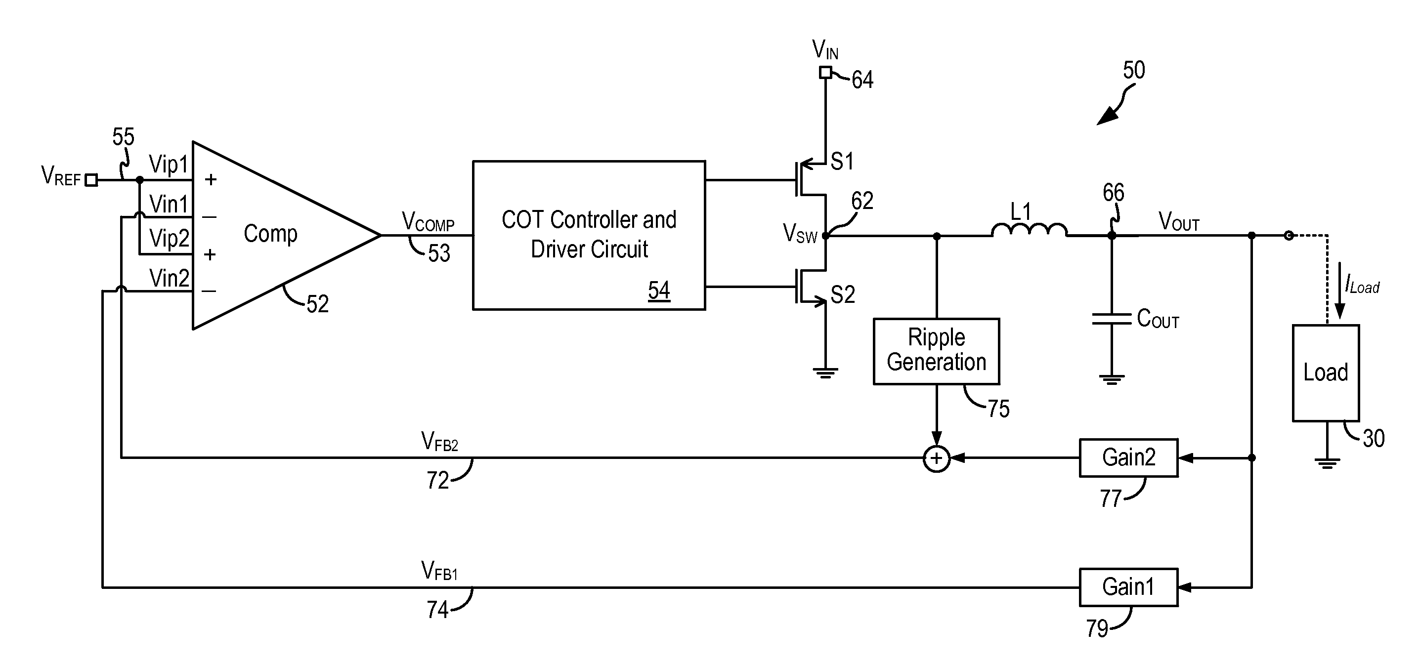
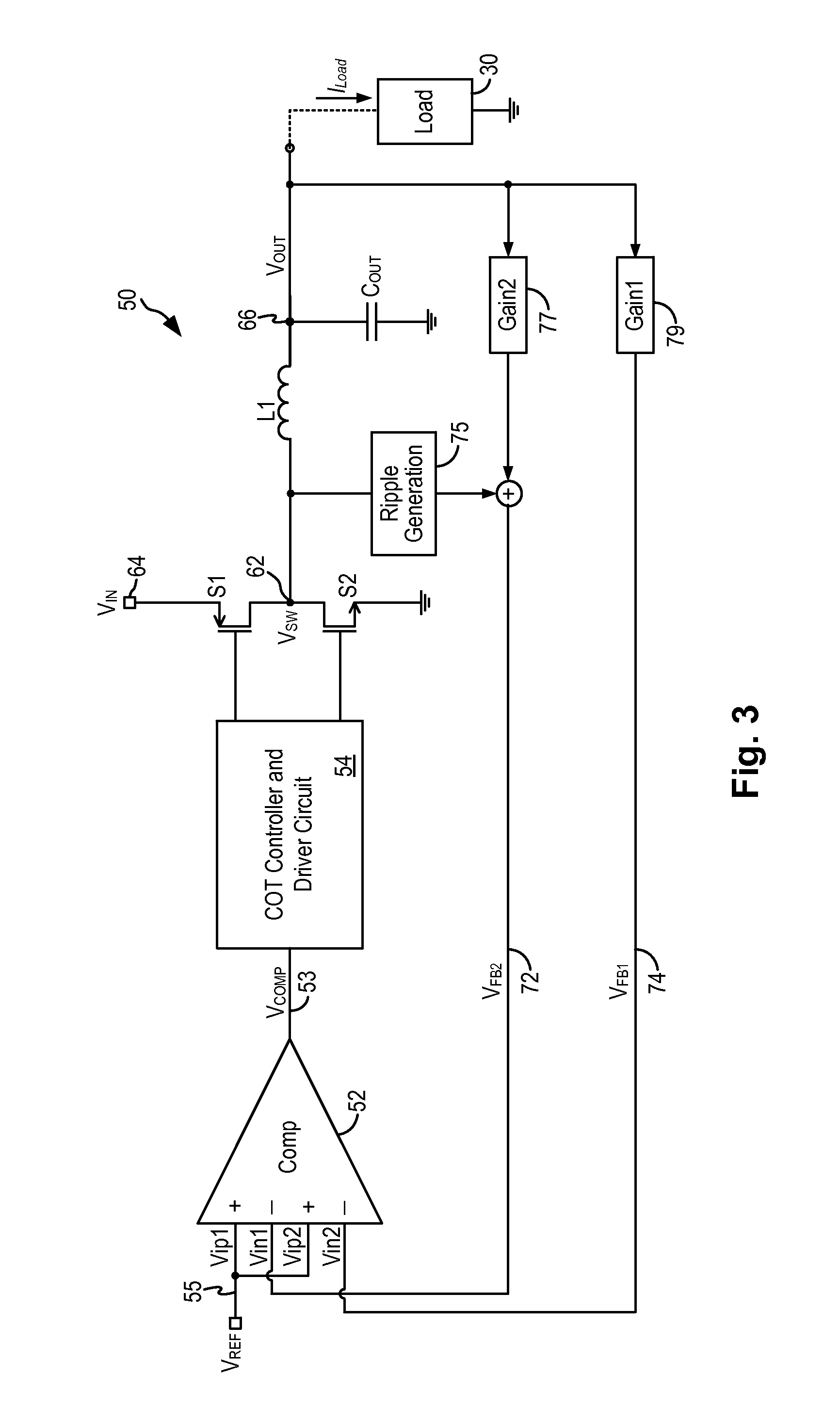
A buck switching regulator includes a feedback control circuit using a four-input comparator to regulate the output voltage to a substantially constant level with reduced voltage offset and with fast transient response. In some embodiments, the buck switching regulator uses the four-input comparator to compare a first feedback signal without ripple and a second feedback signal with injected ripple components to a reference level. The four-input comparator generates an output signal to control the switching of the power switches. The buck switching regulator generates an output voltage with increased accuracy and fast transient response. Furthermore, the buck switching regulator can be used with output capacitor having any value of ESR.

Description

BACKGROUND OF THE INVENTION[0001]Switch mode power supplies or switching regulators, also referred to as DC to DC converters, are often used to convert an input supply voltage to a desired output voltage at a voltage level appropriate for the internal circuitry of an integrated circuit. For example, a 5 volts supply voltage provided to an integrated circuit may need to be reduced to 2.8 volts on the IC chip to operate the internal circuitry on the chip. A switching regulator provides power supply function through low loss components such as capacitors, inductors, and transformers, and power switches that are turned on and off to transfer energy from the input to the output in discrete packets. A feedback control circuit is used to regulate the energy transfer to maintain a constant output voltage within the desired load limits of the circuit.[0002]A switching regulator can be configured to step up the input voltage or step down the input voltage or both. Specifically, a buck switchi...

Claims


Application Information

Patent Timeline
IPC IPC(8): H02M3/158H02M1/00
CPCH02M3/158H02M3/156H02M1/0025H02M1/007
Inventor XUE, DASHUNMACLEAN, WILLIAM
Owner MICREL
Learn More