Adaptive resolution in optical flow computations for an image processing system

an image processing system and computation technology, applied in image analysis, image enhancement, instruments, etc., can solve the problems of failure to compute optical flow, mobile platforms may not be able to fully utilize optical flow,

Inactive Publication Date: 2015-09-17
QUALCOMM INC
View PDF11 Cites 13 Cited by
  • Summary
  • Abstract
  • Description
  • Claims
  • Application Information

AI Technical Summary

Benefits of technology

[0006]Embodiments disclosed herein may relate to a method for determining optical flow from a plurality of images and may include receiving a first image frame from a first plurality of images, where the first plurality of images have a first resolution and a first frame rate. The method may also include receiving a second image frame from a second plurality of images, where the second plurality of images have a second resolution less than the first resolution and a second frame rate greater than the firs

Problems solved by technology

However, as in computer vision implementations, mobile platforms may be unable to fully utilize optical flow due to computational requirements and limitations of particular input image

Method used


Image

  • Adaptive resolution in optical flow computations for an image processing system
  • Adaptive resolution in optical flow computations for an image processing system
  • Adaptive resolution in optical flow computations for an image processing system

Examples


Embodiment Construction

[0018]Reference throughout this specification to “one embodiment,”“an embodiment,”“one example,” or “an example” means that a particular feature, structure, or characteristic described in connection with the embodiment or example is included in at least one embodiment of the present invention. Thus, the appearances of the phrases “in one embodiment” or “in an embodiment” in various places throughout this specification are not necessarily all referring to the same embodiment. Furthermore, the particular features, structures, or characteristics may be combined in any suitable manner in one or more embodiments. Any example or embodiment described herein is not to be construed as preferred or advantageous over other examples or embodiments.

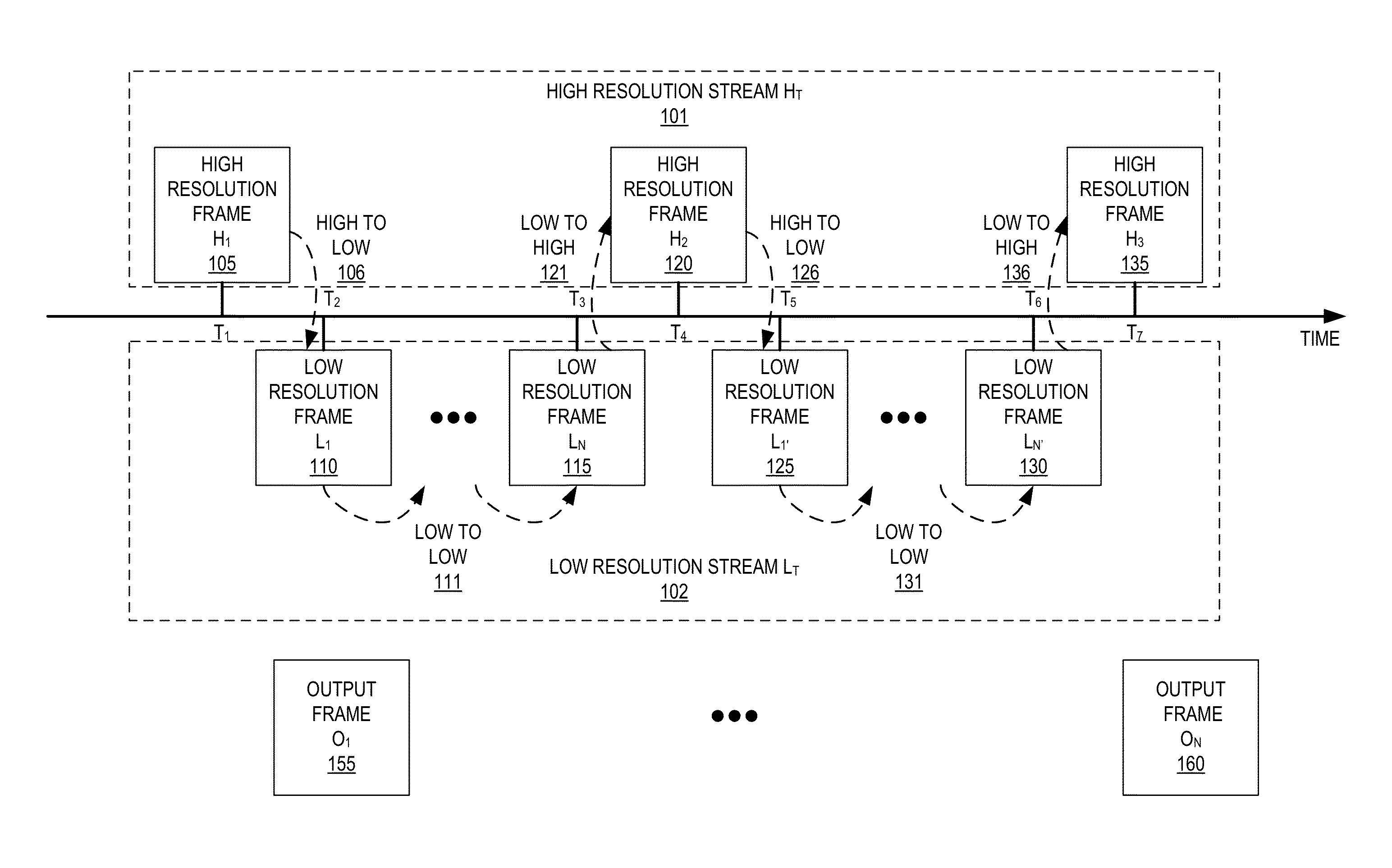
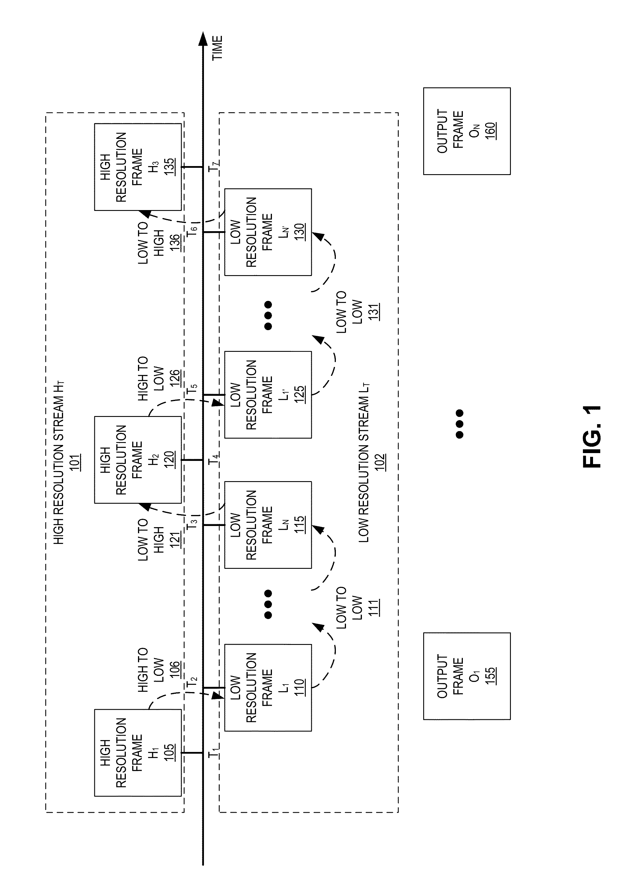
[0019]Typical optical flow implementations, especially in lower power environments such as mobile platforms or devices, are optimized for a constant frame rate, low-resolution image stream. For example, the computation of optical flow in a mobile plat...


PUM


Abstract

A method, device, and apparatus for determining optical flow from a plurality of images is described and includes receiving a first image frame from a first plurality of images, where the first plurality of images have a first resolution and a first frame rate. A second image frame may be received from a second plurality of images, where the second plurality of images have a second resolution less than the first resolution and a second frame rate greater than the first frame rate. A first optical flow may be computed from the first image frame to the second image frame. Additionally, the based at least in part on the first optical flow from the first image frame to the second image frame, a third image frame may be output as part of an output stream. The output stream may have a frame rate greater than or equal to the first frame rate, where the third image frame has a resolution greater than or equal to the second resolution.

Description

CROSS-REFERENCE TO RELATED APPLICATION[0001]This application claims the benefit of U.S. Provisional Application No. 61 / 954,431, filed Mar. 17, 2014.TECHNICAL FIELD[0002]This disclosure relates generally to computer vision based object recognition applications, and in particular but not exclusively, relates to computing optical flow in an image processing system.BACKGROUND INFORMATION[0003]A wide range of electronic devices, including mobile wireless communication devices, personal digital assistants (PDAs), laptop computers, desktop computers, digital cameras, digital recording devices, and the like, may employ machine / computer vision techniques to provide versatile imaging capabilities. For example, some machine vision techniques assist users in recognizing landmarks, identifying particular persons, provide augmented reality (AR) applications, and a variety of other tasks.[0004]Motion tracking of objects, or environments from one image frame to another may be leveraged by one or mo...

Claims


Application Information

Patent Timeline
IPC IPC(8): G06T7/20G06T19/00
CPCG06T7/2073G06T7/2093G06T19/006G06T2207/20004G06T2207/30244G06T2207/20016G06T2207/10016G06T3/40G06T7/20G06T7/207G06T7/292
Inventor GRASMUG, PHILIPPSCHMALSTIEG, DIETERHAUSWIESNER, STEFANKALKOFEN, DENIS
Owner QUALCOMM INC
Why Eureka
Try Eureka