
Touch panel, display device, optical sheet, method for selecting optical sheet, and method for manufacturing optical sheet

a technology for display devices and optical sheets, applied in the field of selecting optical sheets, can solve the problems of deteriorating resolution, inability to obtain optical sheets suitable for ultrahigh-definition display elements having a pixel density of 300 ppi or more, and inability to prevent the scintillation of image light, suppress the reflection of external light, and impart high-degree anti-glare properties

Active Publication Date: 2015-09-17
DAI NIPPON PRINTING CO LTD
View PDF1 Cites 15 Cited by
  • Summary
  • Abstract
  • Description
  • Claims
  • Application Information

AI Technical Summary

Benefits of technology

The present invention provides a touch panel, display device, and optical sheet that can prevent the scintillation of image light in ultrahigh-definition display elements having a pixel density of 300 ppi or more, even if the display elements have an uneven structure. Additionally, the invention improves anti-glare properties and can efficiently manage the qualities of optical sheets. The manufacturing method of the optical sheet can also impart a variety of characteristics such as anti-glare properties and efficiently manufacture optical sheets that can prevent the scintillation of image light in ultrahigh-definition display elements having a pixel density of 300 ppi or more.

Problems solved by technology

In addition, there is a tendency for great internal haze to deteriorate resolution, and such a tendency is stronger in ultrahigh-definition display elements.
Therefore, even when attention is paid to internal haze as in the patent documents 1 and 2, it has not been possible to obtain an optical sheet suitable for ultrahigh-definition display elements having a pixel density of 300 ppi or more.
However, even with the techniques of the patent documents 3 to 9, the prevention of scintillation in ultrahigh-definition display elements having a pixel density of 300 ppi or more is not possible.
First, regarding the causes of scintillation, the distortion of transmitted light caused by the uneven shape when image light passes through an optical sheet having surface unevenness is considered as a cause.
However, with this design, while it was possible to prevent scintillation in display elements having a low pixel density, it was not possible to prevent scintillation in ultrahigh-definition display elements having a pixel density of 300 ppi or more.

Method used


Image

  • Touch panel, display device, optical sheet, method for selecting optical sheet, and method for manufacturing optical sheet
  • Touch panel, display device, optical sheet, method for selecting optical sheet, and method for manufacturing optical sheet
  • Touch panel, display device, optical sheet, method for selecting optical sheet, and method for manufacturing optical sheet

Examples


example 1

[0342]A coating fluid for anti-glare layers 1 having the following formulation was applied onto a transparent base material (80 μm-thick triacetyl cellulose resin film (TAC), manufactured by Fujifilm Corporation, TD80UL), was dried at 70° C. at a wind speed of 5 m / s for 30 seconds, and then an ultraviolet ray was applied in a nitrogen atmosphere (having an oxygen concentration of 200 ppm or less) so that the integral of light reached 100 mJ / cm2 so as to form an anti-glare layer, thereby obtaining an optical sheet. The film thickness of the anti-glare layer was 7.5 μm.

[0343]

Pentaerythritol triacrylate10 parts(manufactured by Nippon Kayaku Co.,Ltd., KAYARAD-PET-30)Urethan acrylate45 parts(manufactured by the Nippon Synthetic ChemicalIndustry Co., Ltd., UV1700B)Photopolymerization initiator 3 parts(manufactured by BASF, IRGACURE184)Silicone-based levelling agent0.2 parts (manufactured by Momentive Performancematerials Inc., TSF4460)Transmissive particles12 parts(manufactured by Sekisui...

example 2

[0344]An optical sheet was obtained in the same manner as in Example 1 except for the fact that the amount of the transmissive particles and the inorganic ultrafine particles in Example 1 were changed to 10 parts and 170 parts.

example 3

[0345]An optical sheet was obtained in the same manner as in Example 1 except for the fact that the amount of the transmissive particles and the inorganic ultrafine particles in Example 1 were changed to 15 parts and 150 parts.


PUM

PropertyMeasurementUnit
inclination angle distributionaaaaaaaaaa

Abstract

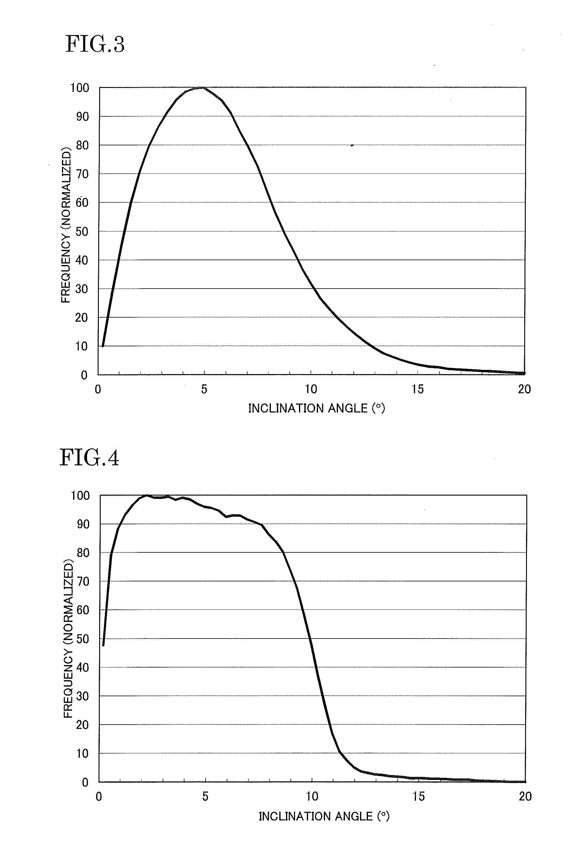
A touch panel capable of imparting a variety of characteristics such as anti-glare properties and preventing the scintillation of image light in ultrahigh-definition display elements having a pixel density of 300 ppi or more is provided.The touch panel includes an optical sheet as a component, in which the optical sheet has an uneven shape on a surface, the uneven shape satisfies at least one condition selected from the following (A) to (C), and the touch panel is used for a front surface of a display element having a pixel density of 300 ppi or more,Condition (A); a gap between inclination angles indicating a half value of a peak value of an inclination angle distribution curve of the uneven shape is in a range of 5 degrees to 15 degrees,Condition (B); an inclination angle indicating an inflection point on a positive direction side of the inclination angle indicating the peak value of the inclination angle distribution curve of the uneven shape is in a range of 4 degrees to 15 degrees, and a difference between the inclination angle indicating the inflection point on the positive direction side and the inclination angle indicating the peak value of the inclination angle distribution curve is in a range of 2.2 degrees to 10 degrees, andCondition (C); the inclination angle indicating the peak value of the inclination angle distribution curve of the uneven shape is in a range of 2 degrees to 8 degrees, skewness of the inclination angle distribution curve of the uneven shape is in a range of 0 degrees to 1.5 degrees, and / or kurtosis of the inclination angle distribution curve of the uneven shape is in a range of 1.5 to 6.

Description

FIELD OF THE INVENTION[0001]The present invention relates to a touch panel, a display device, an optical sheet, a method for selecting an optical sheet, and a method for manufacturing an optical sheet.BACKGROUND OF THE INVENTION[0002]Recently, mobile information terminal devices which have an interactive communication function and are equipped with a transparent touch panel for information display and information input, which are represented by tablet PCs and smartphones, have been widely distributed not only in Japan but also across the globe.[0003]In spite of the presence of resistance film-type touch panels which are excellent in terms of cost, electrostatic capacitance-type touch panels, particularly, projection electrostatic capacitance-type touch panels have been increasingly demanded as transparent touch panels since gesture operations such as multi-touch are possible and the image quality of ultrahigh-definition display elements is not easily impaired.[0004]In some cases, an...

Claims


Application Information

Patent Timeline
Patent Type & Authority Applications(United States)
IPC IPC(8): G02B1/11B05D5/06G06F3/041B29D11/00
CPCG02B1/11B29D11/0073G06F3/0412B29D11/0074B05D5/06B29D11/00865G06F3/045G02B5/0221G02B5/0268G06F3/044G06F2203/04103G02F1/133507
Inventor FURUI, GENTSUJIMOTO, JUNNAITOU, AYA
Owner DAI NIPPON PRINTING CO LTD
Learn More