
Sheath for protecting against fire

Active Publication Date: 2015-09-17
TECALEMIT AEROSPACE
View PDF11 Cites 10 Cited by
  • Summary
  • Abstract
  • Description
  • Claims
  • Application Information

AI Technical Summary

Benefits of technology

The invention is a protective sheath for fluid transporting pipes that is designed to withstand fire. It is made of two layers: a flame-proof non-flammable layer made of carbon and a heat insulation layer made of a knitted fabric with air bubbles. The non-flammable layer covers the entire pipe and is made of carbon fibers to provide complete protection from flames. The heat insulation layer is made of refractory material that decreases the transmission of heat to other layers, increasing resistance to fire. Overall, this sheath offers better protection for pipes in the event of a fire.

Problems solved by technology

However, these pipes and conventional protection sheaths have a relatively important mass, due to the silicone used as protective material against fire.
These conventional pipes and protection sheaths hence offer a limited response to the issue of reducing the mass of aircrafts.
Furthermore, although the silicone provides efficient heat protection against fire, silicone however has a limited response to protection against flames.
In fact, the drawback of silicone is that it becomes friable in contact with a flame, so much so that as a result of vibrations on an aircraft during flight, a silicone protection sheath subjected to a prolonged contact with flames may disintegrate, and thereby expose the layers of an underlying duct of the sheath to the flames.
The security imperatives, in particular of fire protection, and economical and environmental imperatives linked to reduction in fuel consumption and hence a decrease in aircraft mass, thus currently result in a conflict to which conventional pipes often do not fully meet in as far as the response to certain requirements is privileged by comparison to others.

Method used


Image

  • Sheath for protecting against fire
  • Sheath for protecting against fire
  • Sheath for protecting against fire

Examples


Embodiment Construction

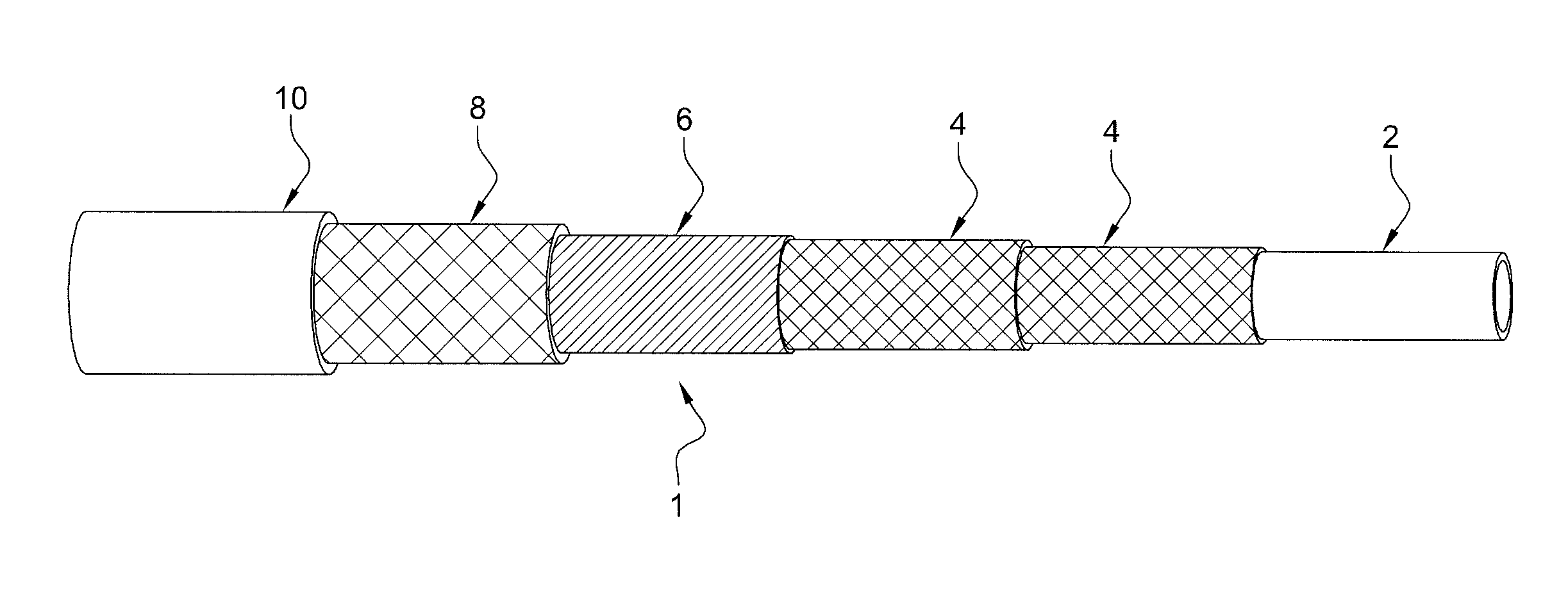
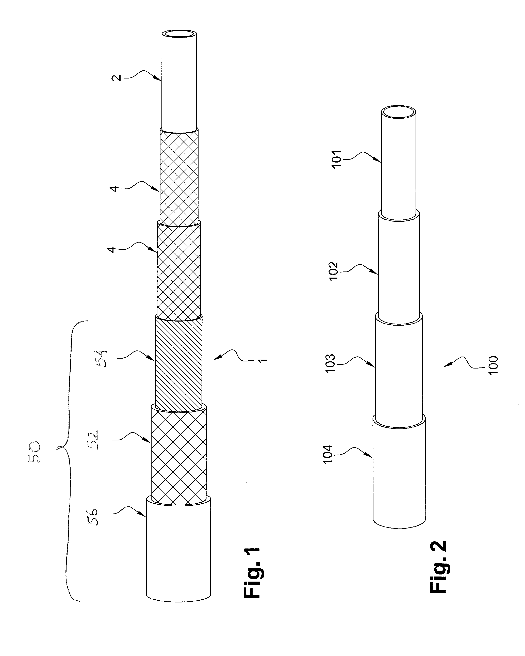
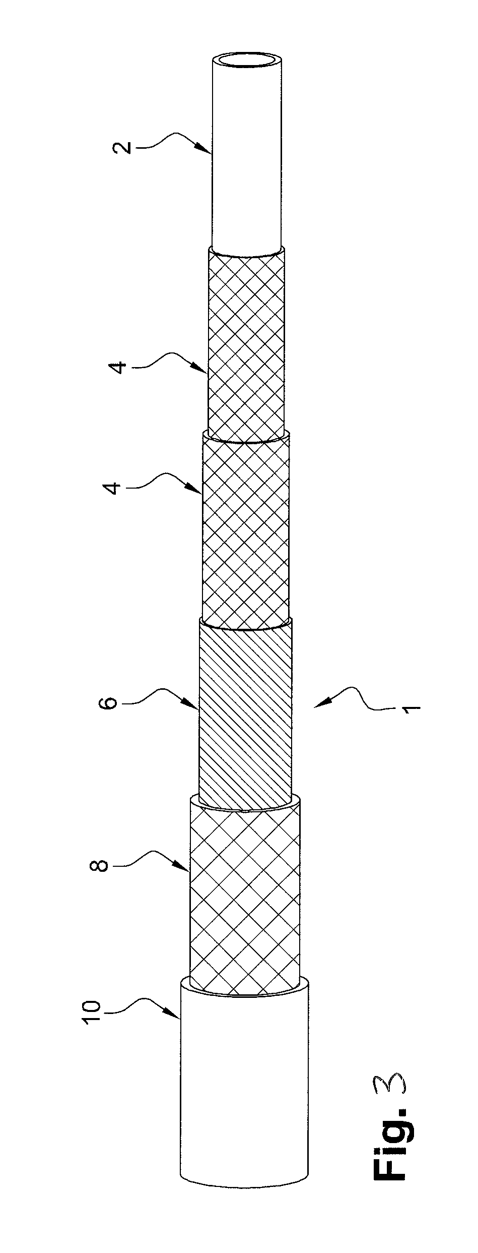
[0086]FIG. 1 shows a composite pipe 1 equipped with a protection sheath 50 according to an embodiment of the invention. This pipe 1 may more particularly correspond to a flexible composite pipe, intended for transporting fluid, such as lubricating or fuel fluid, in an aircraft, in particular for an aircraft engine.

[0087]The sheath 50 comprises a non-flammable layer 52.

[0088]The non-flammable layer 52 is flame-proof. The non-flammable layer 52 is composed of carbon only.

[0089]The sheath 50 also comprises a heat insulation layer 54, arranged beneath the non-flammable layer 52.

[0090]The heat insulation layer 54 corresponds to a knitted fabric.

[0091]The knitted fabric comprises a plurality of stitches and air trapped in the plurality of stitches, in such a manner that the heat insulation layer 54 comprises at least by volume 70% of air.

[0092]The volume of air in the knitted fabric is measured by calculating the section of the knitted fabric layer on the basis of the difference between t...


PUM

PropertyMeasurementUnit
Fractionaaaaaaaaaa
Pressureaaaaaaaaaa
Diameteraaaaaaaaaa

Abstract

The invention relates to a protective sheath (50) for covering a fluid-transporting pipeline, comprising a flame-proof, non-inflammable layer (52) and a heat insulation layer (54) arranged beneath the non-inflammable layer, the non-inflammable layer consisting only of carbon and the heat insulation layer comprising a knitted fabric, the knitted fabric comprising a plurality of stitches and air trapped within the plurality of stitches such that the heat insulation layer comprises at least 70 vol. % of air. Furthermore, the non-inflammable layer comprises carbon fibres providing 100% coverage in order to protect the heat insulation layer from contact with flames.

Description

TECHNICAL FIELD[0001]The present invention relates to a sheath for protecting against fire, a method of producing a flexible composite pipe comprising this sheath, and a composite pipe, in particular a flexible composite pipe intended for transporting a fluid in an aircraft, comprising this sheath.BACKGROUND[0002]The pipes used for applications in the aeronautics field must meet certain requirements such as resistance to fire for predetermined security time periods.[0003]Furthermore, within a global context of reducing fuel consumption, the requirement of reducing the mass of aircrafts is becoming a priority.[0004]It is known of transporting fluids in an aircraft by means of flexible pipes, comprising for example stainless steel braids for pressure resistance within the pipe and a heat protection sheath, of silicone, intended for protecting the pipes during a fire by meeting the requirements.[0005]However, these pipes and conventional protection sheaths have a relatively important m...

Claims


Application Information

Patent Timeline
IPC IPC(8): F16L57/04D04C1/12D04B1/22F16L11/12
CPCF16L57/04D04B1/225D04C1/12F16L11/125B32B1/08B32B27/12B32B27/322B32B2262/106B32B2307/304B32B2307/3065B32B2307/54B32B2307/718B32B2597/00B32B2605/18B64D37/20B64D37/32F16L11/082F16L11/086
Inventor COLCOMBET, THIERRY
Owner TECALEMIT AEROSPACE
Learn More