
Fire resistant oil spill barrier

Inactive Publication Date: 2012-03-01
APPLIED FABRIC TECH
View PDF13 Cites 0 Cited by
  • Summary
  • Abstract
  • Description
  • Claims
  • Application Information

AI Technical Summary

Benefits of technology

[0008]An advantage of the present invention is that it is functional, durable, and reusable a number times.
is that it is functional, durable, and reusable a number times.

Problems solved by technology

Also, because burning the oil in an uncontrolled manner is dangerous, it is important that the fire be contained.

Method used


Image

  • Fire resistant oil spill barrier
  • Fire resistant oil spill barrier
  • Fire resistant oil spill barrier

Examples


example

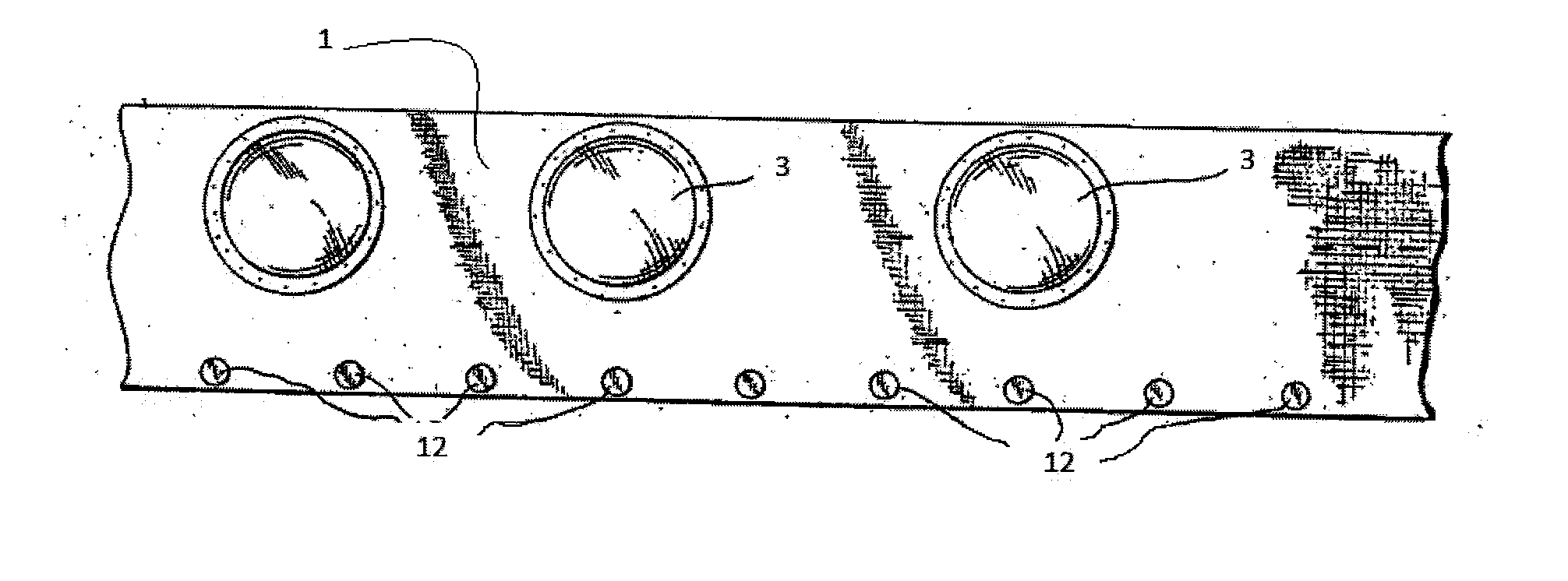
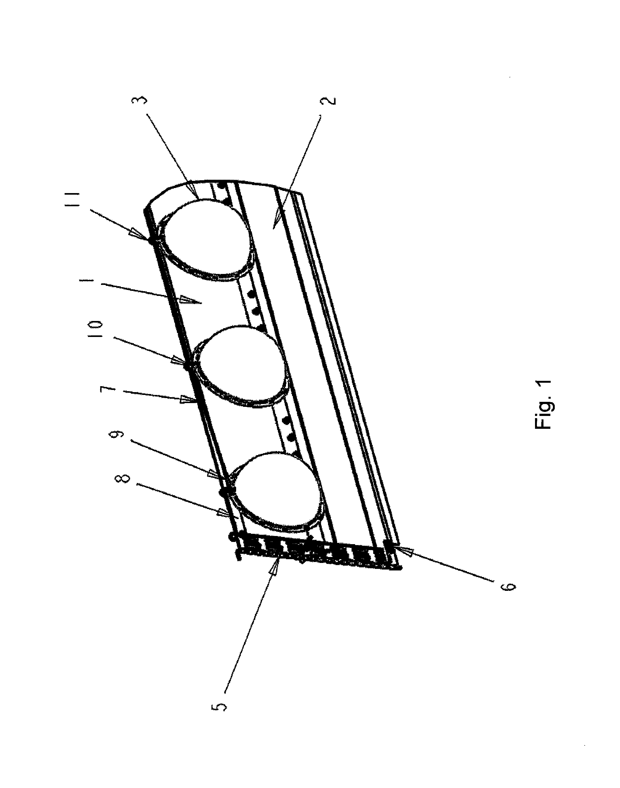
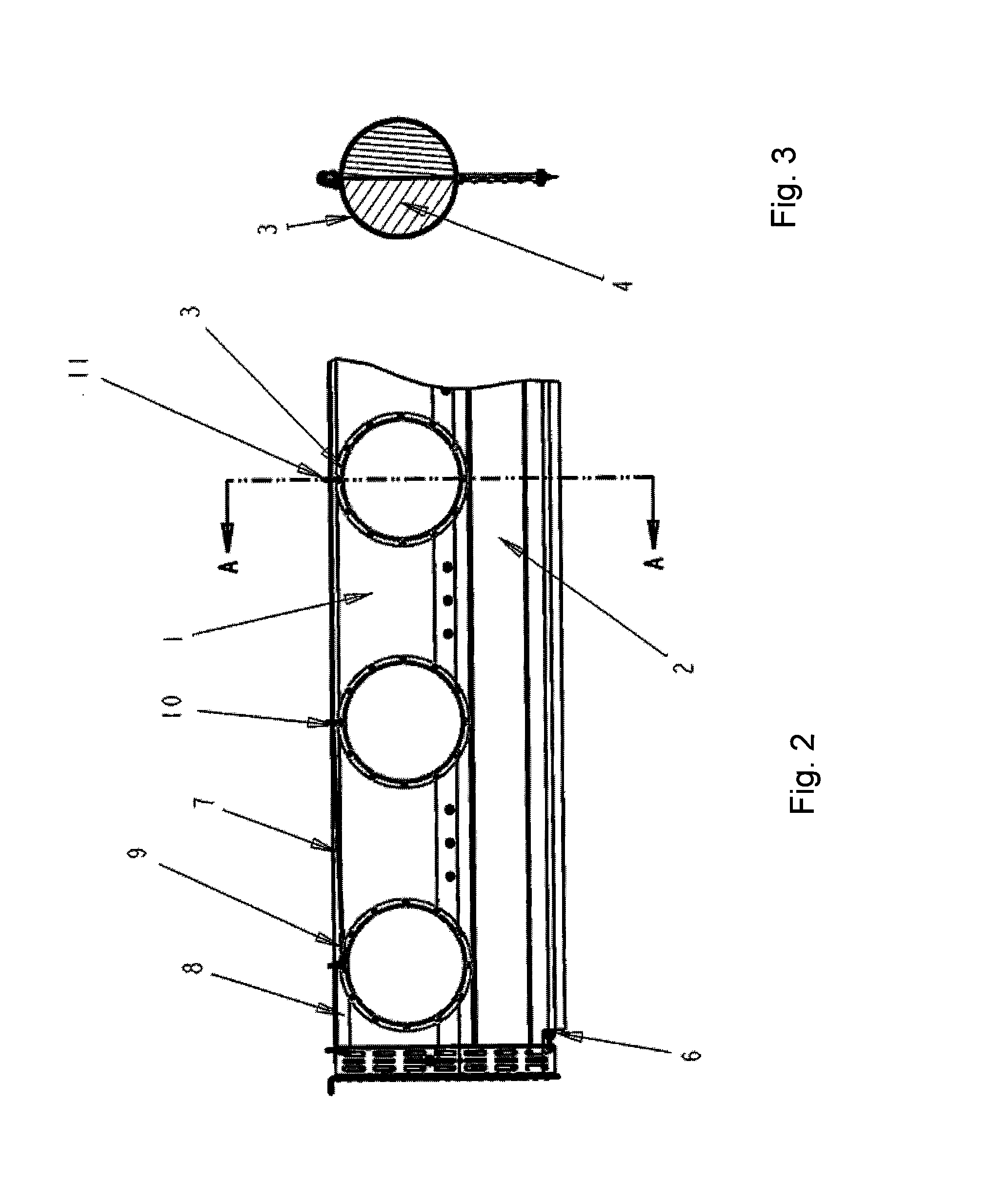
[0041]A woven fabric is provided, characterized by its fire resistance light weight and durability. The fabric has a warp of 100% Iconel Wire and a filling of a blend of Iconel and Fiberfrax. The wire serves to provide support to the fabric structure while exposed to fire, and also has very good tensile strength properties, even at elevated temperatures. The “wire screen effect” of the interwoven wires helps to maintain integrity even after prolonged fire exposure. The Fiberfrax filling material is a stuffer yarn to help the wire screen remain impermeable after exposure to burning. It also provides a base for a polymeric resin coating to adhere to.

[0042]The fabric is coated in a conventional manner with a high-temperature resistant polyimide resin (2.5 to 4.0% weight add on). The barrier is prepared by mechanically attaching a 12″ wide strip of the fabric to a non-fireproof fabric, which serves to provide a below the waterline barrier. Identical hemispherical floats are mechanically...


PUM

PropertyMeasurementUnit
Temperatureaaaaaaaaaa
Linear densityaaaaaaaaaa

Abstract

A fire-resistant barrier for the containment of marine oil spills having a first and second end, a length of interwoven high-temperature resistant yarns and metallic wires, coated with a high-temperature resistant synthetic polymeric resin connecting the first and second ends, a plurality of fire-resistant buoyancy devices and a tension member connecting the first end to the fire-resistant buoyancy devices most proximate the first end.

Description

FIELD OF THE INVENTION[0001]This invention relates to floating oil spill barriers and in particular relates to a fire-resistant, buoyant, oil spill barrier for the containment of marine oil spills.BACKGROUND OF THE INVENTION[0002]One method to clean marine oil spills is to burn off the oil sitting on the surface of the water. If the oil is dispersed, it may be necessary to first concentrate the oil by skimming the surface of the water to bring a more concentrated amount of oil into a particular region. Also, because burning the oil in an uncontrolled manner is dangerous, it is important that the fire be contained.[0003]Therefore, a fire-resistant device for concentrating and containing oil is desired.[0004]Further, a flexible fire-resistant device that is resistant to tearing is desired.SUMMARY OF THE INVENTION[0005]The invention comprises, in one form thereof, a fire-resistant, portable, barrier for the containment of marine oil spills. The barrier being a continuous length of a fi...

Claims


Application Information

Patent Timeline
IPC IPC(8): E02B15/06B23P25/00
CPCE02B15/0814Y10T29/49885E02B15/0821Y02A20/204
Inventor LANE, PETER
Owner APPLIED FABRIC TECH
Learn More