
Method for producing an escape route marking for airplanes, and said escape route marking

a technology for airplane escape routes and escape routes, applied in mass transit vehicle lighting, luminescence, lighting applications, etc., can solve the problem of no longer providing rectangular furniture, and achieve the effect of less likely to injure themselves

Active Publication Date: 2015-09-10
LUFTHANSA TECH AG
View PDF5 Cites 1 Cited by
  • Summary
  • Abstract
  • Description
  • Claims
  • Application Information

AI Technical Summary

Benefits of technology

The patent text discusses the trend towards using curved furniture in airplanes to improve safety and aesthetics. However, this change in design requires flexibility in customizing the shape of escape route markings. The technical effect of the patent is to provide a solution for designing flexible and customizable escape route markings for airplanes.

Problems solved by technology

In particular, there is a trend to no longer provide rectangular furniture, but rather also to use curved furniture contours.

Method used


Image

  • Method for producing an escape route marking for airplanes, and said escape route marking
  • Method for producing an escape route marking for airplanes, and said escape route marking
  • Method for producing an escape route marking for airplanes, and said escape route marking

Examples


Embodiment Construction

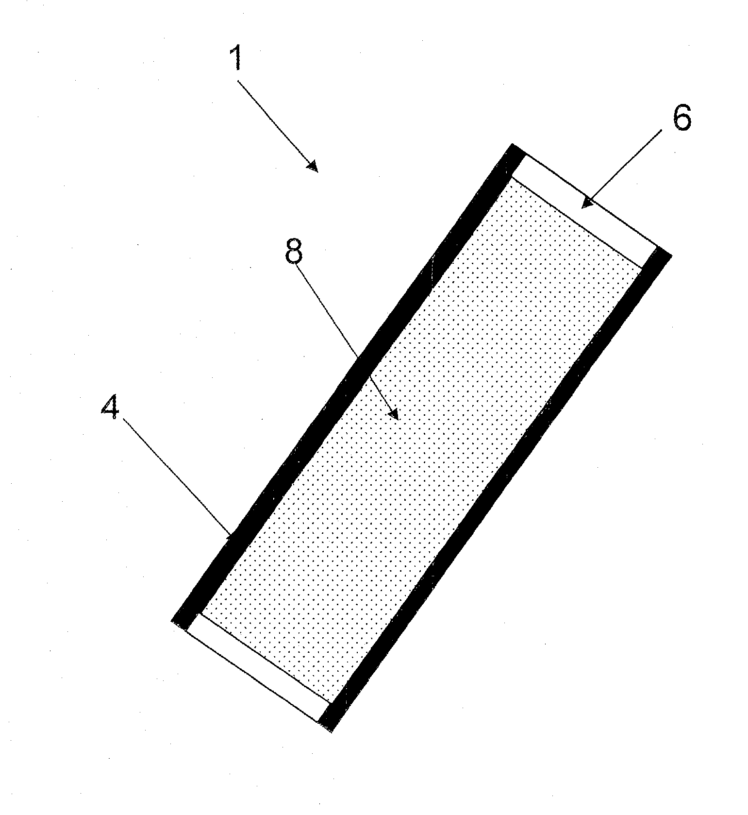
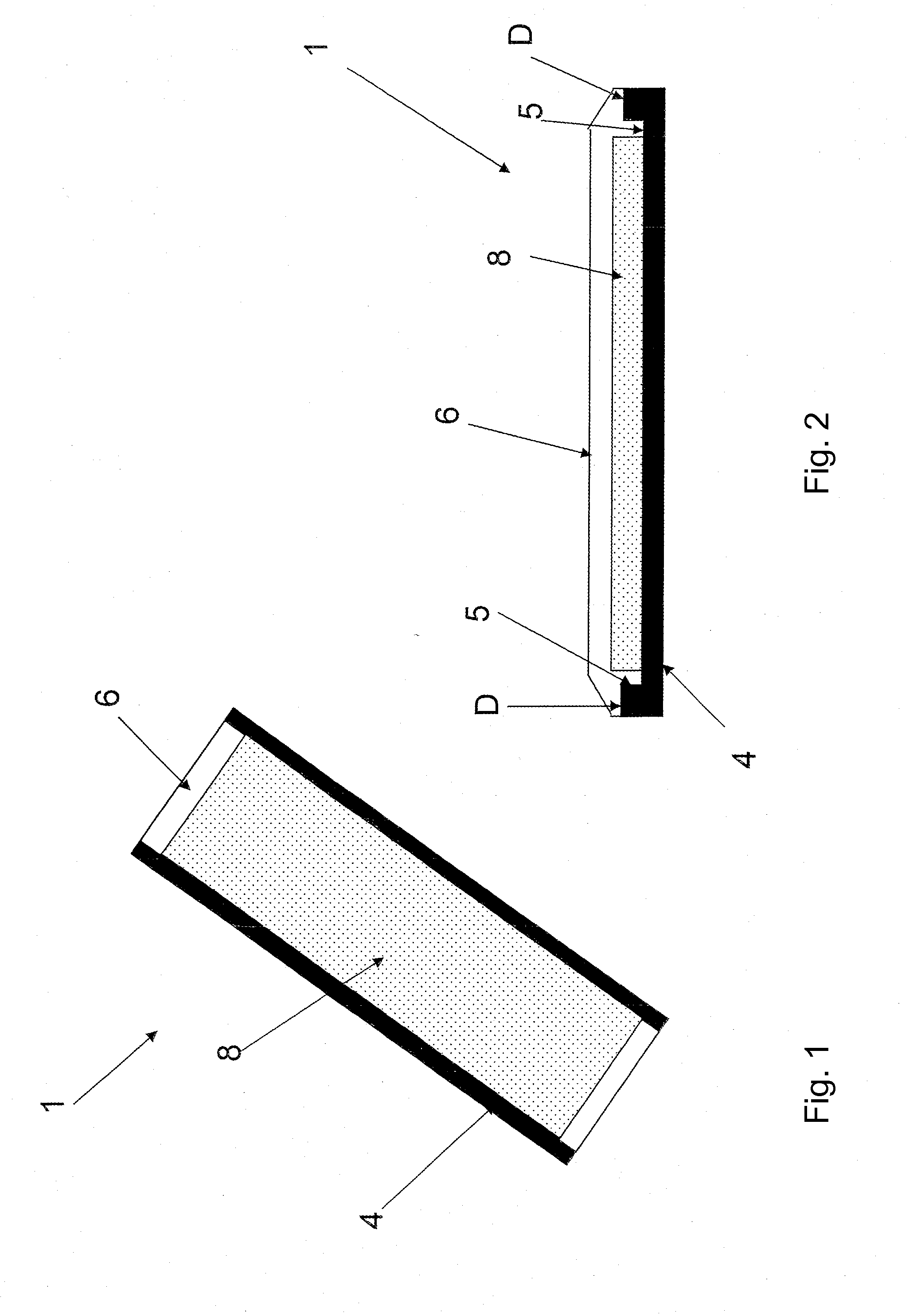
[0041]FIG. 1 shows an escape route marking 1 in a straight mold with a dyed, transparent covering 6. An afterglowing, photoluminescent material 8, which is in turn arranged lying in a planar manner on a supporting element 4, is arranged below the dyed, transparent covering 6. The photoluminescent material 8 is provided in a transparent supporting element according to FIG. 1. The supporting element can be designed transparently, but can also be designed non-transparently when it is connected with the substrate in the laid state of the escape route marking. Alternatively, the photoluminescent material 8 is also poured into the transparent supporting element. The photoluminescent material 8 can then be made for example of photoluminescent pigments, which are incorporated in a polymer matrix, preferably a silicone or polycarbonate matrix.

[0042]FIG. 2 shows a cross-sectional representation of the escape route marking according to FIG. 1. It can be seen in the cross-section that the suppo...


PUM

PropertyMeasurementUnit
photoluminescentaaaaaaaaaa
transparentaaaaaaaaaa
radiiaaaaaaaaaa

Abstract

A method for producing an escape route marking in a heatable and malleable support mold is described. The escape route marking has a transparent covering, a supporting element and a photoluminescent material. The method includes procuring the heatable and malleable support mold, inserting a supporting element into the support mold, arranging the photoluminescent material on the supporting element, arranging the transparent covering on the supporting element, heating and deforming the escape route marking in the support mold and solidifying the escape route marking in the support mold in a predetermined position. The resulting escape route marking is also described.

Description

FIELD OF THE DISCLOSURE[0001]The present invention relates to a method for producing an escape route marking for airplanes and an escape route marking produced according to the method.BACKGROUND[0002]Escape route markings are of particular importance in emergency situations in which a power supply cannot always be guaranteed. It is known to arrange photoluminescent strips on the floor inside the airplane for escape route marking in airplanes, which is also called emergency marking. Photoluminescence is occasionally termed afterglow and / or phosphorescence. The safety-related requirements are specified for example in German Industrial Standard DIN 67 510. The strips are placed on the floor in a straight line and, in an emergency, indicate to passengers and the flight crew the path to ways out and emergency exits. In the past when designing airplanes, photoluminescent strips became increasingly prevalent because they are failsafe and can work without a power supply.[0003]An emergency l...

Claims


Application Information

Patent Timeline
Patent Type & Authority Applications(United States)
IPC IPC(8): F21K2/00B29C51/12B29C51/30B29C51/00F21W107/30
CPCF21K2/00B29C51/002B29C51/12B29C51/30B29L2009/00F21W2101/06B29K2069/00B29K2883/005B29K2995/0035F21W2111/00B29L2031/772B60Q3/46B60Q3/78C09D5/22F21W2107/30
Inventor BIEHL, TORBENLIEROW, HANS-CHRISTIAN
Owner LUFTHANSA TECH AG
Learn More