
Direct use of acoustic power in stirling engine for heat removal

Inactive Publication Date: 2015-09-03
GONEN ERAN
View PDF1 Cites 4 Cited by
  • Summary
  • Abstract
  • Description
  • Claims
  • Application Information

AI Technical Summary

Benefits of technology

The patent is about a new way to cool down Stirling engines using the sound waves they produce. This improves the engine's efficiency. The sound waves are used to drive a piston or an acoustic pump to move liquid through a cooling device. This method eliminates the need for the sound waves to be converted into electricity and then back into pumping work.

Problems solved by technology

However, by using this configuration there is an inherent increased power loss, since the engine is using some of its end product (electricity) for its continuous operation.

Method used


Image

  • Direct use of acoustic power in stirling engine for heat removal
  • Direct use of acoustic power in stirling engine for heat removal
  • Direct use of acoustic power in stirling engine for heat removal

Examples


Embodiment Construction

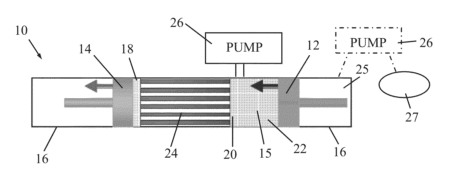
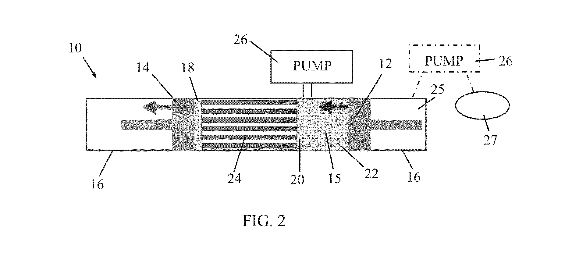
[0014]Reference is now made to FIG. 2, which illustrates a block diagram of Stirling engine 10, constructed and operative in accordance with a non-limiting embodiment of the present invention.

[0015]As in a typical Stirling engine, the Stirling engine 10 has a piston 12 and a displacer 14 that move in phased reciprocating motion within cylinders 16 which, in some embodiments of the Stirling engine, may be a single cylinder. A working fluid 15 contained within cylinders 16 is constrained by seals from escaping around piston 12 and displacer 14. The working fluid 15 is chosen for its thermodynamic properties, e.g., helium at a pressure of several atmospheres. The position of displacer 14 governs whether working fluid 15 is in contact with a hot interface (or hot heat exchanger) 18 or a cold interface (or cold heat exchanger) 20, corresponding respectively to the interfaces at which heat is supplied to and extracted from working fluid 15. The volume of working fluid 15 governed by the p...


PUM


Abstract

A Stirling engine includes a piston and a displacer that move in phased reciprocating motion within one or more cylinders. A working fluid is contained within the one or more cylinders, and a position of the displacer causes the working fluid to be in contact with either a hot heat exchanger or a cold heat exchanger. A volume of the working fluid governed by a position of the piston is referred to as a compression space. The piston, the displacer and the working fluid operate in a thermodynamic cycle that generates acoustic wave power. An acoustic pump is driven by the acoustic wave power.

Description

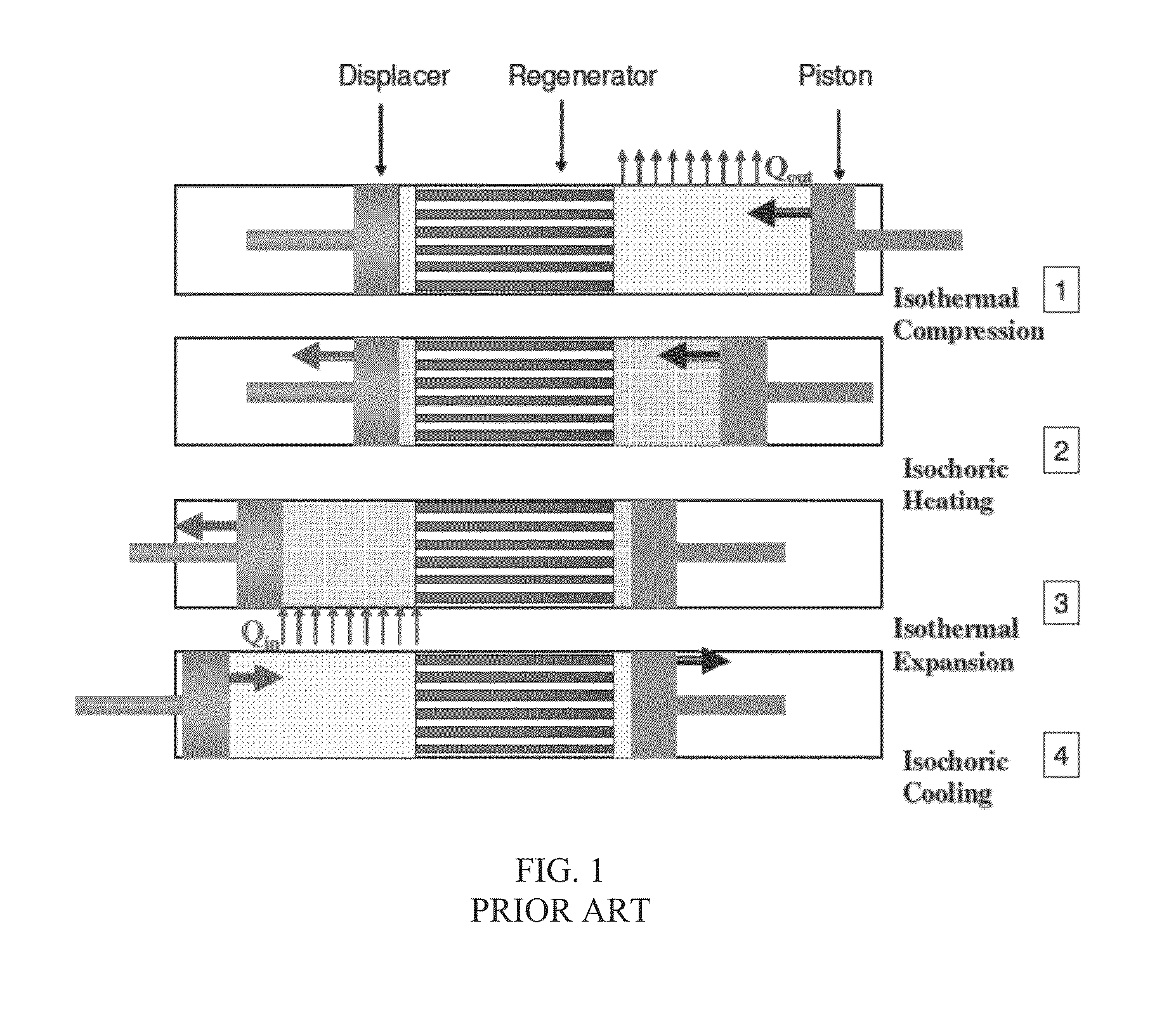
FIELD OF THE INVENTION[0001]The present invention relates generally to Stirling engines, and particularly to utilizing acoustic power in such an engine for heat removal.BACKGROUND OF THE INVENTION[0002]The Stirling cycle is a well-known four-part thermodynamic process, typically operating on a gas, to produce work, or conversely to effect heating or refrigeration. The four parts, shown in FIG. 1, are isothermal expansion, isochoric heat extraction, isothermal compression, and isochoric heat addition. The process is closed, in that the gas remains within the system performing the cycle at all times during the cycle.[0003]A typical Stirling engine has pistons that respond to the heating / expansion and cooling / contraction of a contained gas as part of the Stirling cycle. The motion of the pistons may provide available work. A regenerative heat exchanger or regenerator increases the engine's thermal efficiency. FIG. 1 shows a Stirling cycle having such a regenerator between two heat exch...

Claims


Application Information

Patent Timeline
IPC IPC(8): F25B9/14
CPCF25B9/14F02G1/043F02G2256/00F02G2280/00
Inventor GONEN, ERAN
Owner GONEN ERAN
Learn More