Method and Apparatus for Improving Engine Performance

Active Publication Date: 2015-05-21
CRAWFORD QUIRT EVAN
View PDF12 Cites 0 Cited by
  • Summary
  • Abstract
  • Description
  • Claims
  • Application Information

AI Technical Summary

Benefits of technology

The invention aims to improve engine performance by adjusting the position of the air flow sensor in the air intake pipe. This is done by repositioning the sensor from its original location to a new position closer to the interior wall surface of the air intake pipe. Additionally, the invention also recommends the use of a spacer to increase the depth of penetration of the air flow sensor into the air intake pipe. This results in a more accurate measurement of air flow, leading to increased engine efficiency.

Problems solved by technology

This means there is a large gap left between the capacity the engines are currently running at, and where their optimal performance could be.
Several attempts have been made to address this issue, but they all involve the internal modification of the air intake pipe, and tend to be complex, unreliable and expensive—both to build and to install.

Method used


Image

  • Method and Apparatus for Improving Engine Performance
  • Method and Apparatus for Improving Engine Performance
  • Method and Apparatus for Improving Engine Performance

Examples


Embodiment Construction

[0016]The following discussion describes in detail one embodiment of the invention and several variations of that embodiment. This discussion should not be construed, however, as limiting the invention to those particular embodiments. Practitioners skilled in the art will recognize numerous other embodiments as well.

Definitions

[0017]As used herein, the following terms and variations thereof have the meanings given below, unless a different meaning is clearly intended by the context in which such term is used.

[0018]The terms “a,”“an,” and “the” and similar referents used herein are to be construed to cover both the singular and the plural unless their usage in context indicates otherwise.

[0019]As used in this disclosure, the term “comprise” and variations of the term, such as “comprising” and “comprises,” are not intended to exclude other additives, components, integers, ingredients or steps.

The Invention

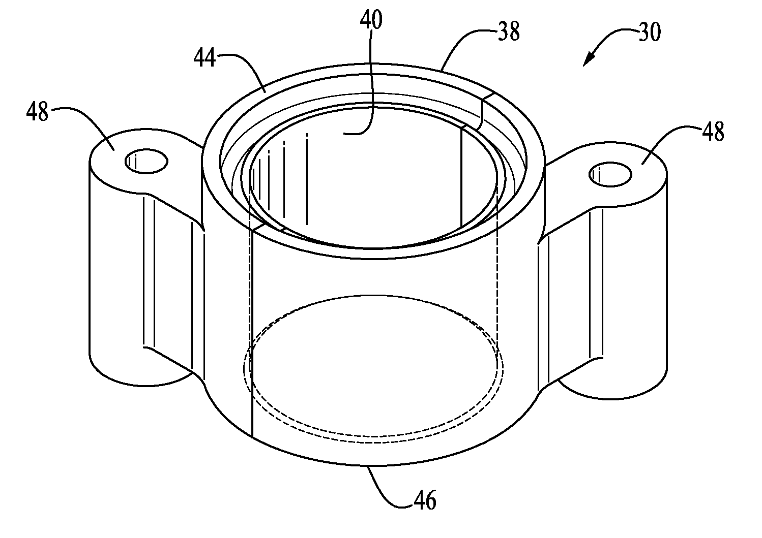
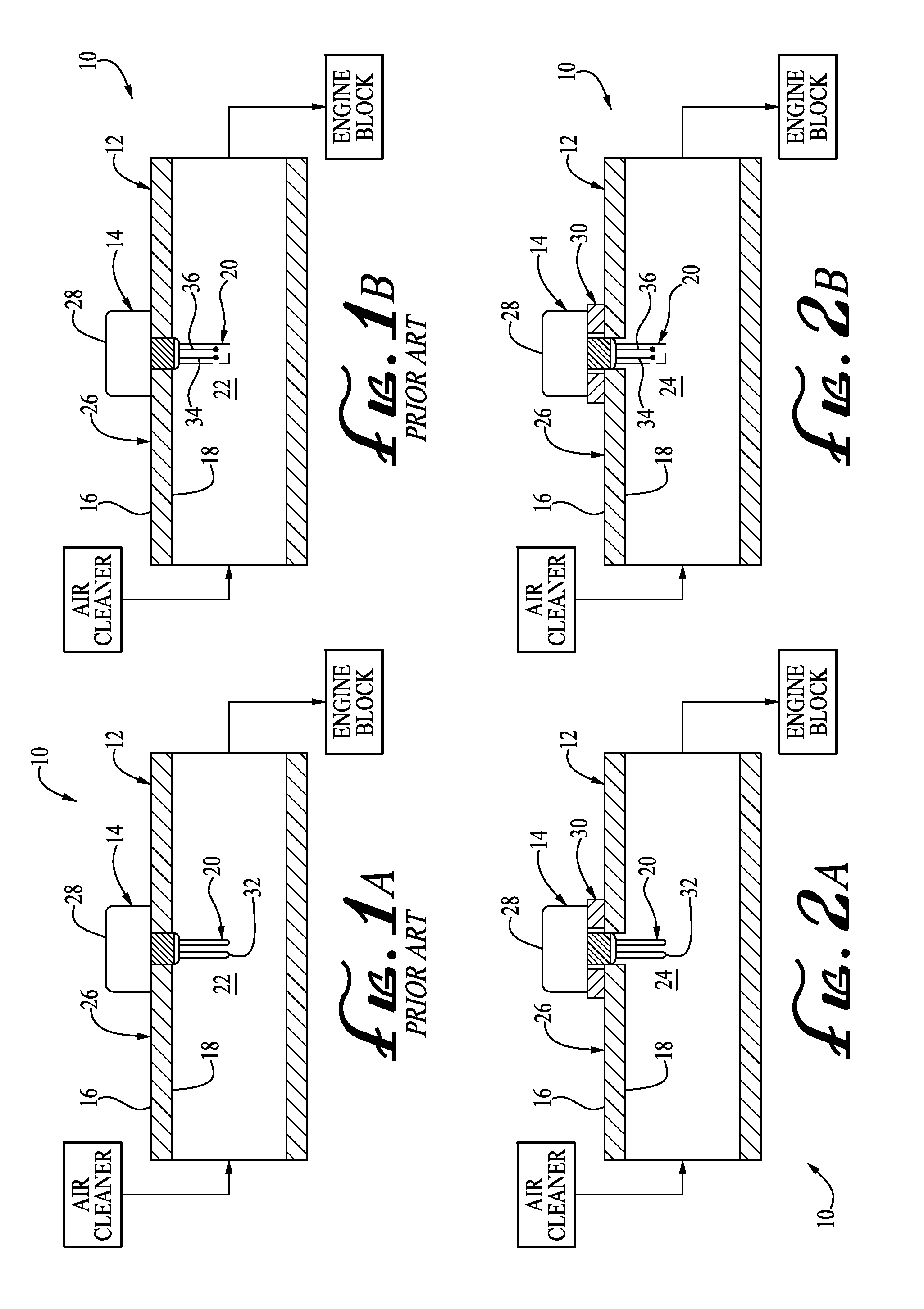
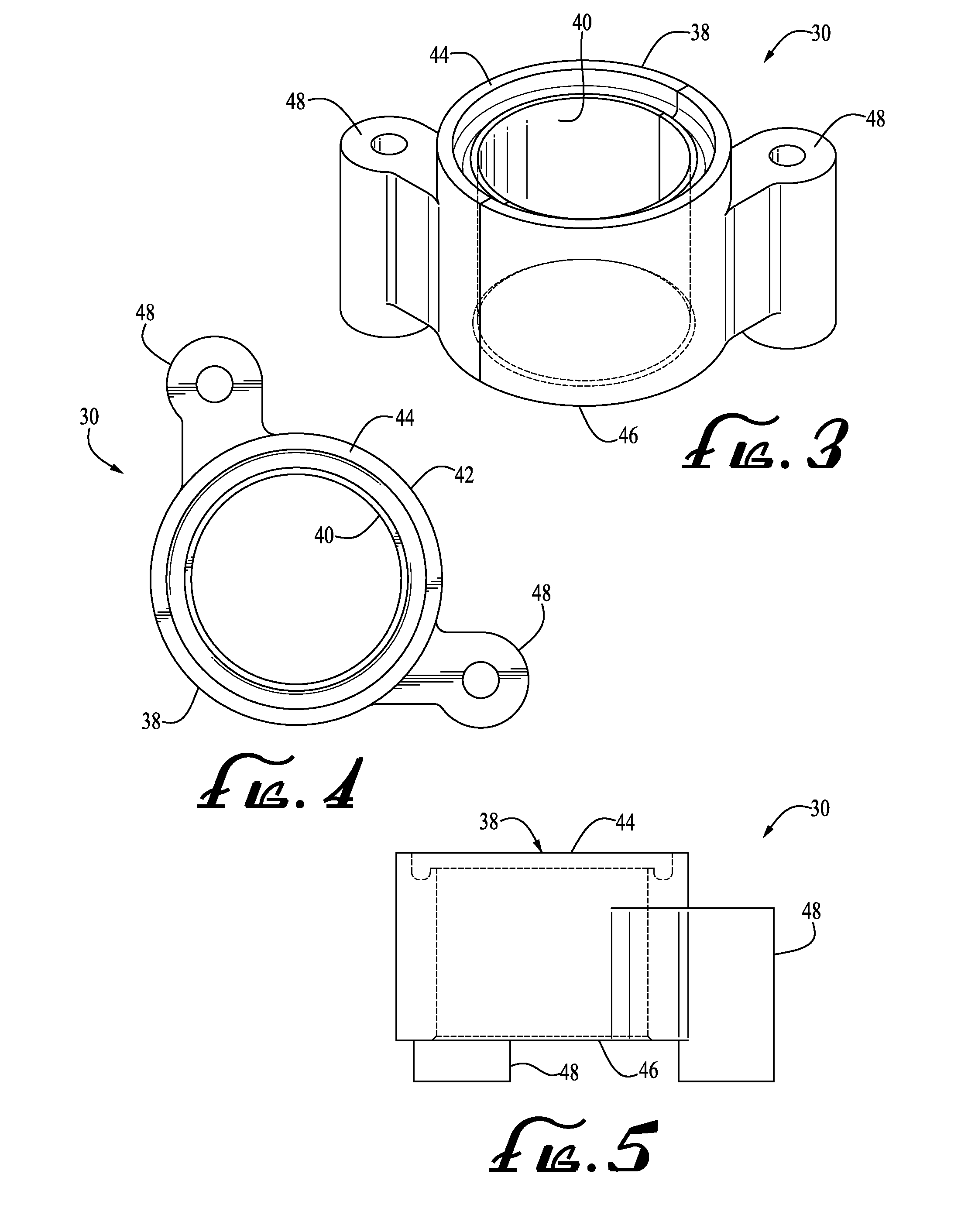
[0020]In one aspect, the invention is a method of modifying an engine 10 after t...


PUM

PropertyMeasurementUnit
Thicknessaaaaaaaaaa

Abstract

A method of modifying an engine after the engine has been initially sold by the manufacturer of the engine, wherein the engine has an air intake pipe and an air flow sensor, wherein the air intake pipe has an exterior wall surface and an interior wall surface, and wherein the air flow sensor has a sensing head disposed at a first location within the air intake pipe spaced apart from the interior wall surface of the air intake pipe, includes the step of: repositioning the sensing head from the first location to a second location, wherein the second location is closer to the interior wall surface of the air intake pipe than the position of the sensing head at the first location.

Description

RELATED APPLICATION[0001]This application claims priority from U.S. Patent Application Ser. No. 61 / 905,038, entitled “Method and Apparatus for Improving Engine Performance,” filed Nov. 15, 2013, the entirety of which is incorporated herein by reference.BACKGROUND OF THE INVENTION[0002]Many automobiles contain mass air flow sensors. Mass air flow sensors are used to determine the mass flow rate of air entering a fuel-injected internal combustion engine. The data that the mass air flow sensor gathers is processed by the engine control unit, which then determines the proper air to fuel ratio necessary for the engine to run at its most efficient level for factory settings.[0003]Most mass air flow sensor heads are located in the air intake pipe of the engine, and are typically placed to read the flow of air flowing through the middle of the pipe. Using this typical depth of penetration of the mass air flow sensor head, most automobile manufacturers have designed their engine control unit...

Claims


Application Information

Patent Timeline
IPC IPC(8): F02M35/10
CPCF02M35/10386F02M35/1034F02M35/10091Y10T29/49817
Inventor CRAWFORD, QUIRT EVAN
Owner CRAWFORD QUIRT EVAN
Why Eureka
Try Eureka