
Rigid endoscope with hermetic seal

a hermetic seal and endoscope technology, applied in the field of hermetic seals, can solve the problems of excessive welding and insufficient welding, and achieve the effects of reliable sealing, simple structure and reliable hermeticity

Active Publication Date: 2015-09-03
FUJIFILM CORP
View PDF0 Cites 13 Cited by
  • Summary
  • Abstract
  • Description
  • Claims
  • Application Information

AI Technical Summary

Benefits of technology

The present invention provides a rigid endoscope with a simple structure that can reliably seal the hermetic shell of the rigid tube. The male and female tapered surfaces are combined to keep the hermetic shell air-tight, ensuring the endoscope can safely contain the imaging module. This improves the reliability of the endoscope and allows for easier maintenance and repair.

Problems solved by technology

Should the clearance be too wide, welding will be insufficient due to the low amount of the transmitted heat.
Should the clearance be too narrow, welding will be excessive due to the high amount of the transmitted heat.

Method used


Image

  • Rigid endoscope with hermetic seal
  • Rigid endoscope with hermetic seal
  • Rigid endoscope with hermetic seal

Examples


1st embodiment

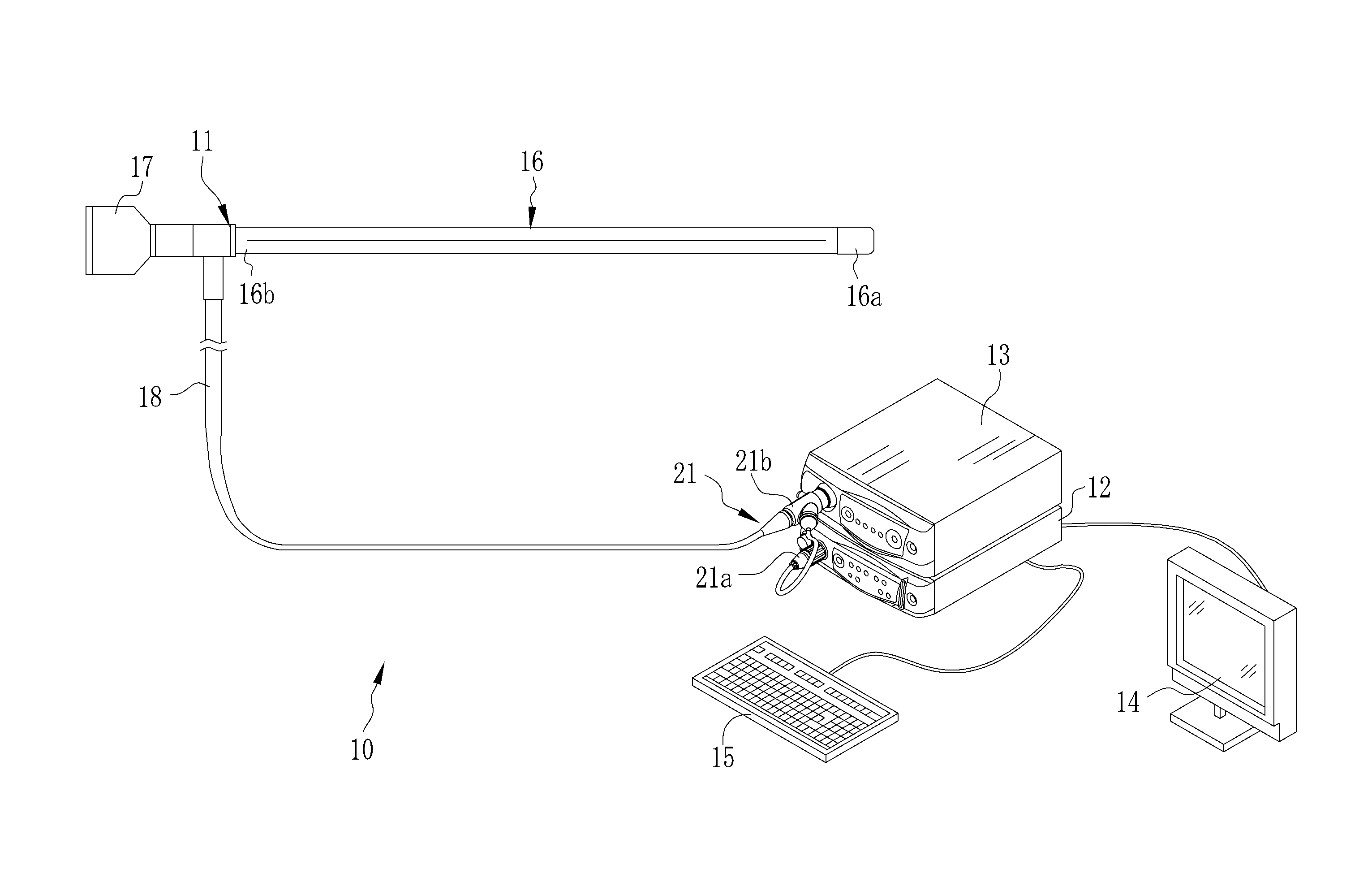
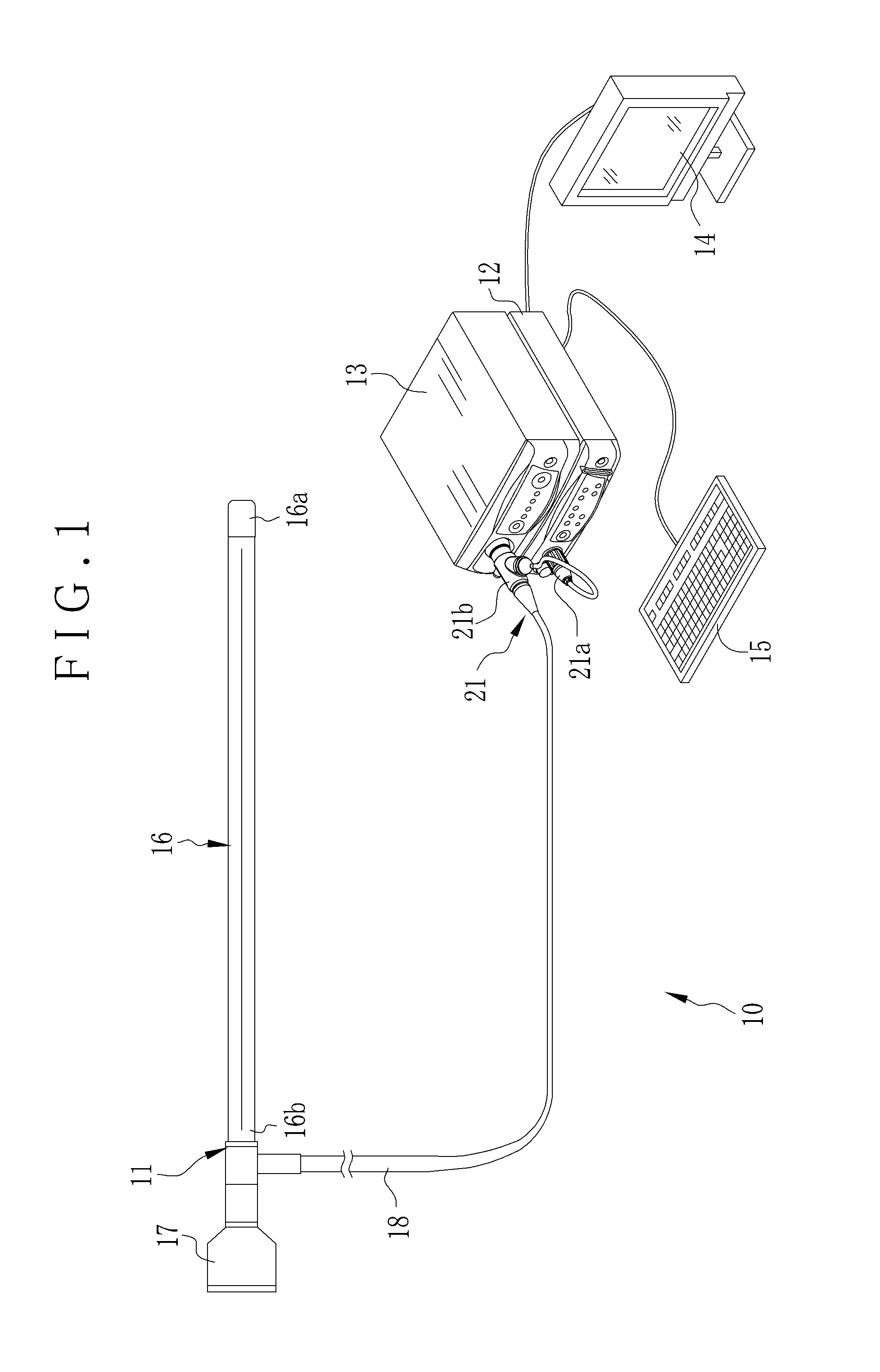
[0041]In FIG. 1, an endoscope system 10 includes a rigid electronic endoscope 11, a processing apparatus 12, a light source apparatus 13 and a monitor display panel 14. The rigid endoscope 11 images an object of interest in a body cavity of a patient. The processing apparatus 12 generates an image according to an image signal of the object from the rigid endoscope 11. The light source apparatus 13 supplies the rigid endoscope 11 with light for illuminating the object to be imaged. The monitor display panel 14, for example, a liquid crystal display panel, displays the image. A user input interface 15 is connected with the processing apparatus 12, for example, a keyboard, mouse and the like.

[0042]The rigid endoscope 11 includes a rigid tube 16 or endoscope tube, a grip handle 17 and a universal cable 18. The rigid tube 16 is used for entry in an abdominal cavity of a patient. The grip handle 17 is disposed at a proximal end 16b of the rigid tube 16. The universal cable 18 is disposed ...

2nd embodiment

[0077]In the above embodiment, the male and female tapered surfaces 71 and 73 are regularly conical. In FIG. 8, another preferred hermetic shell 80 (case or container) is illustrated. In a male / female coupling arrangement, a female tapered surface 82 as a concave wall (female type) of a receiving opening in the hermetic shell 80 is hemispherical. A sealed terminal device 81 or lead-through device (sealing closure device) is combined with the hermetic shell 80. A male tapered surface 83 of a plug head (male type) of the sealed terminal device 81 is hemispherical. In case the sealed terminal device 33 is fitted in the hermetic shell 31, no gap occurs between the male and female tapered surfaces 82 and 83 while the female tapered surface 82 is fitted on the male tapered surface 83. The same effect as the above embodiment can be obtained. Note that the lead-through conductors (terminal pins), connecting lines and the like are omitted from FIG. 8 in the same manner as FIGS. 7A and 7B.

[00...


PUM


Abstract

A rigid endoscope includes an imaging module and a hermetic shell for containing the imaging module. A connecting line is contained in the hermetic shell, and has first and second ends. The first end is connected to the imaging module. A receiving opening is formed in the hermetic shell. A female tapered surface is formed inside the receiving opening. A sealed terminal device is connected electrically with the second end of the connecting line, for hermetically closing the receiving opening. A male tapered surface is formed on the sealed terminal device, for retaining the sealed terminal device in the receiving opening by engagement with the female tapered surface, to keep the hermetic shell air-tight. Preferably, the male and female tapered surfaces are attached together by laser welding. Also, the sealed terminal device includes a lead-through conductor.

Description

CROSS-REFERENCE TO RELATED APPLICATION[0001]This application claims priority under 35 USC 119 from Japanese Patent Application No. 2014-038851, filed 28 Feb. 2014, the disclosure of which is incorporated by reference herein.BACKGROUND OF THE INVENTION[0002]1. Field of the Invention[0003]The present invention relates to a rigid endoscope with hermetic seal. More particularly, the present invention relates to a rigid endoscope of which a hermetic shell in a rigid tube can be sealed reliably with a simple structure.[0004]2. Description Related to the Prior Art[0005]A rigid electronic endoscope includes a rigid tube or endoscope tube and a grip handle. The rigid tube is used for entry in a body cavity of a patient. The grip handle is disposed at a proximal end of the rigid tube. The grip handle is connected to a light source apparatus for supply of light and to a processing apparatus for forming an image of an object. The rigid tube has a tip device. Window components (window plates) ar...

Claims


Application Information

Patent Timeline
IPC IPC(8): A61B1/00A61B1/05
CPCA61B1/00071A61B1/00114A61B1/05A61B1/0011A61B1/00124A61B1/051
Inventor KIDO, TAKASHI
Owner FUJIFILM CORP
Learn More