
Underwater Electronics Connector and Methods

a technology of electronics connectors and underwater water, applied in the field of electrical connectors, can solve the problems of difficult separation, difficult to grasp the connector for separation, and not so simple and easy to retrieve, and achieve the effect of increasing the taper

Inactive Publication Date: 2015-08-27
THE UNITED STATES OF AMERICA AS REPRESENTED BY THE SECRETARY OF THE NAVY
View PDF9 Cites 0 Cited by
  • Summary
  • Abstract
  • Description
  • Claims
  • Application Information

AI Technical Summary

Benefits of technology

The patent describes an underwater connection system with male and female connectors that have an increasing taper shape when viewed in top plan. This is achieved by using a rubber housing with a wedge-shaped opening. The taper can be linear or curved, depending on the user's needs. The connectors can be inline or right-angle connectors, depending on the space constraints. The technical effect of this invention is to provide a reliable and flexible connection system for underwater devices, allowing for easy and secure connection in a variety of situations.

Problems solved by technology

Although these types of connectors can be simple and easy to deploy, they are often not so simple and easy to retrieve.
Disassembly of the male and female ends of this type of connector that have previously been deployed underwater or that have been connected for long periods of time tend to be very difficult to separate, as there can be minimal surface area to hold on to.
Additionally, marine growth may have fouled the connector, which can make it difficult to grip the connector for separation.
When the connector is stuck, operators will often wrongly use a flat screw driver to pry the ends of the connector apart.
This could easily damage the connector body.
In the case of right angle connectors, improper disassembly can result in putting a torque on the body of the connector or rotating the seal and threads, which rigidly fasten the connector and create a watertight seal.

Method used


Image

  • Underwater Electronics Connector and Methods
  • Underwater Electronics Connector and Methods
  • Underwater Electronics Connector and Methods

Examples


Embodiment Construction

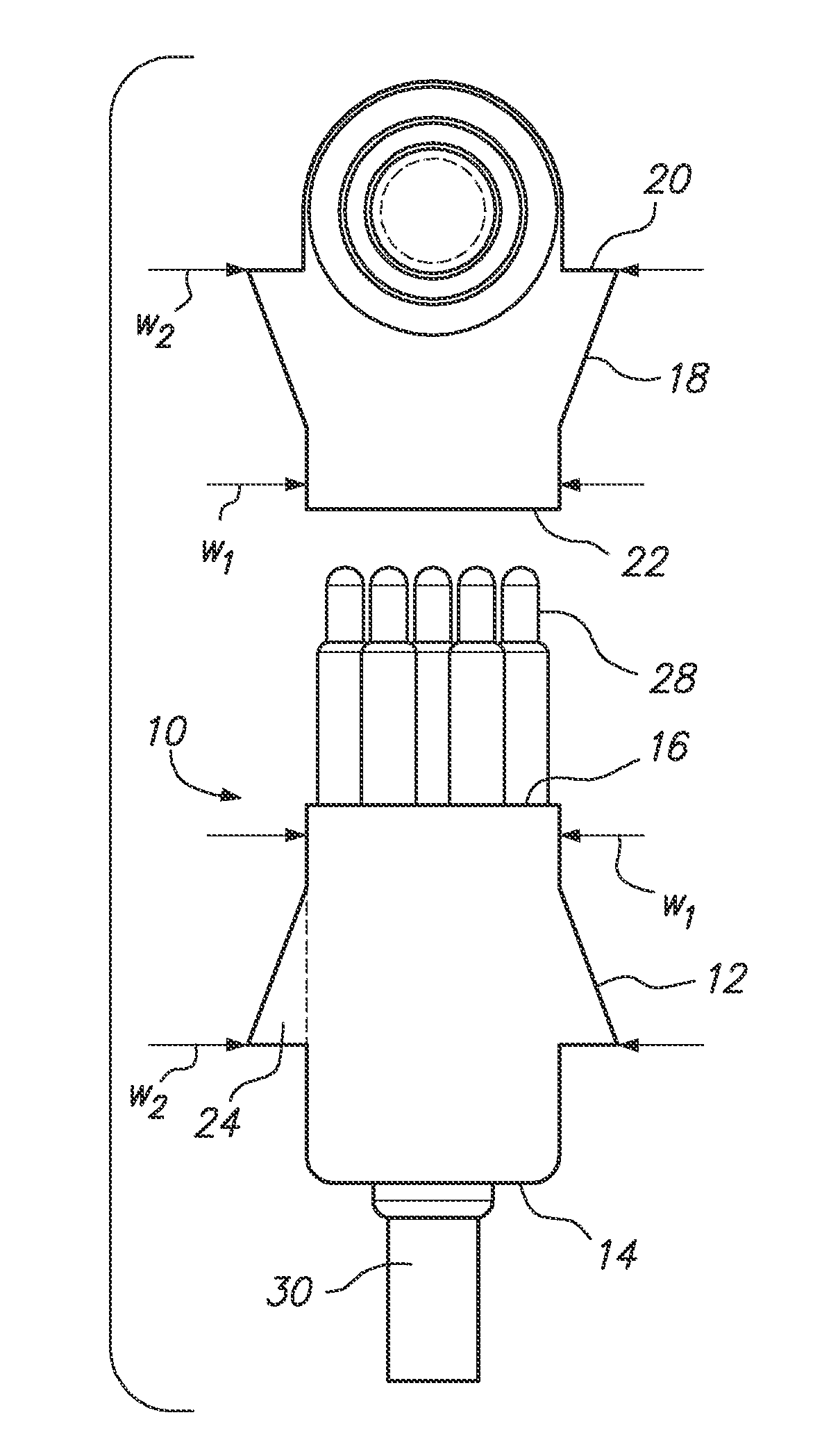
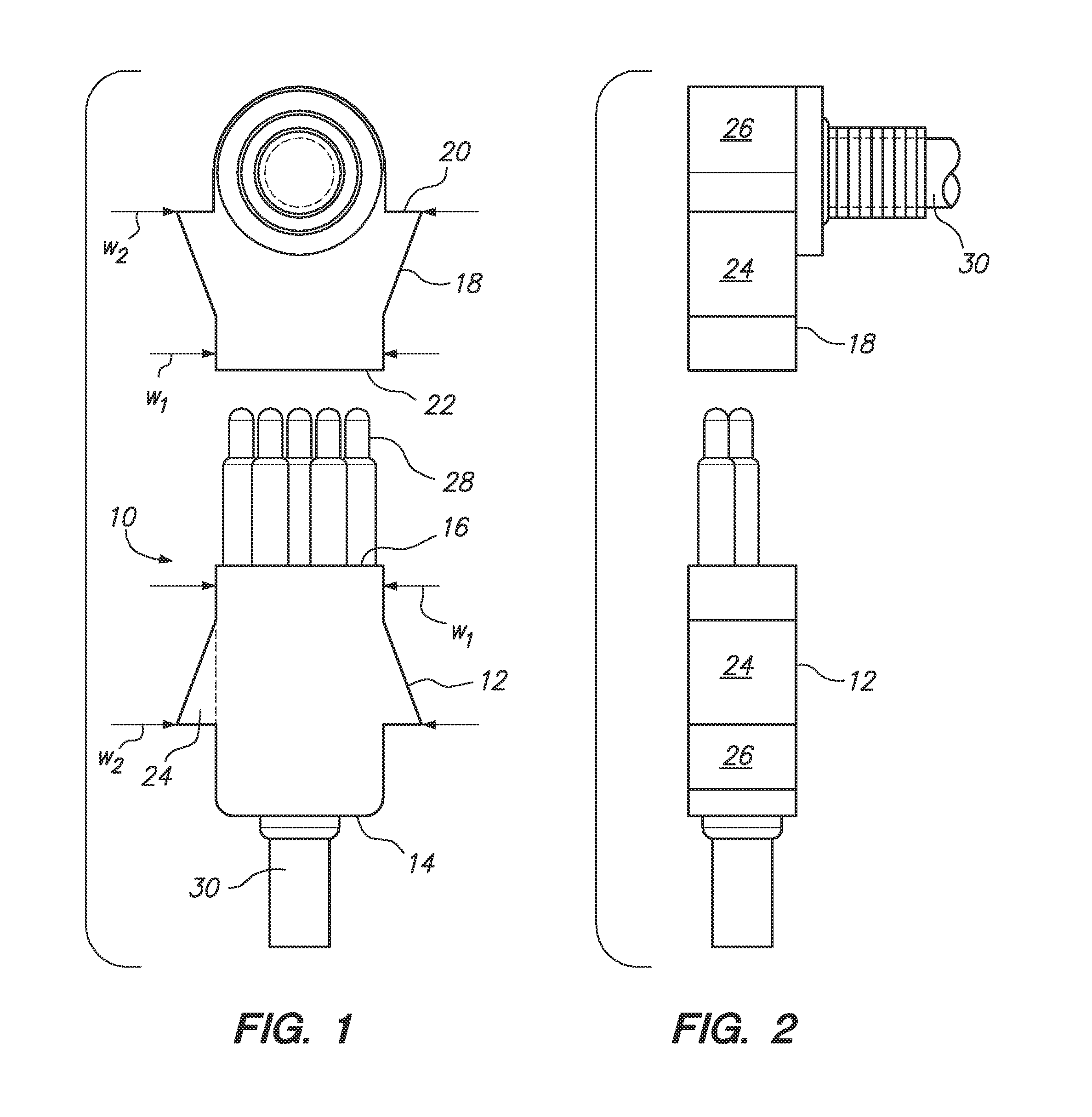
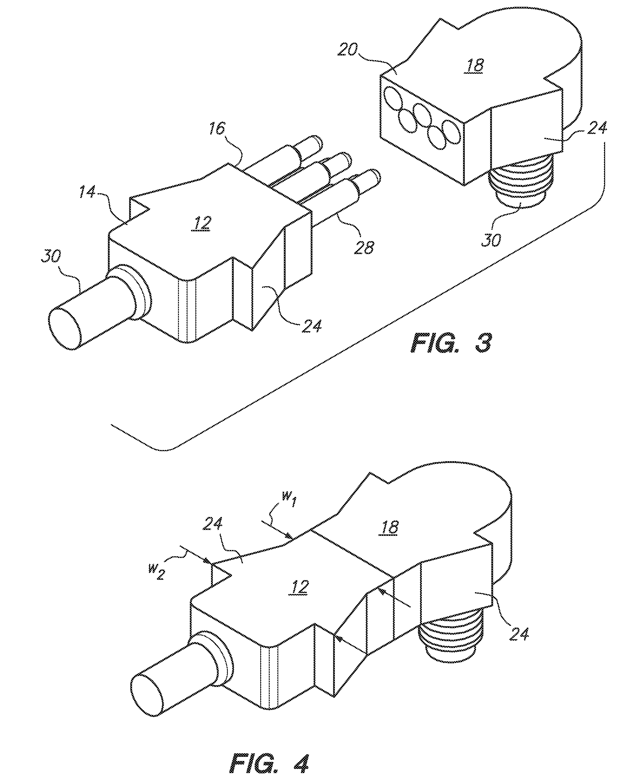
[0015]Referring initially to FIGS. 1-3, an improved underwater electronics connection system according to several embodiments of the present invention is shown and is generally designated by reference character 10. As shown in FIGS. 1-3, system 10 can include a male connector 12 with a proximal end 14 and distal end 16, and a female connector 18 having a proximal end 20 and a distal end 22.

[0016]Either of the male connector 12 or the female connector 18 can be formed with a decreasing wedge 24, as shown in FIGS. 1-3. With this configuration, the male connector can have an increasing taper when viewed in top plan from a minimum width w1 at distal end 16 to a maximum width w2 near proximal end 14. Similarly, female connector 18 can have an increasing taper when viewed in top plan from a minimum width w1 at distal end 22 to a maximum width w2 near proximal end 20.

[0017]The wedge 24 can be attached to rubber housing 26 using glue or other means known in the art, or alternatively rubber ...


PUM

PropertyMeasurementUnit
widthaaaaaaaaaa
right-angleaaaaaaaaaa
volumeaaaaaaaaaa

Abstract

An underwater connection system and methods can include a male connector having a proximal end and a distal end and a female connector having a proximal end and a distal end. At least one of the male connector or the female connector can have an increasing taper when viewed in top plan, from a minimum width at its distal end to a maximum width at its proximal end. To do this, the male or female connector can be formed with a surrounding rubber housing. The rubber housing can be formed with a wedge that is integral to the rubber housing to establish the increasing taper. The taper can be linear or curved, according to the needs of the user, and either or the male connector or female connector can be inline or right-angle connectors, according to the system design and space constraints.

Description

FEDERALLY-SPONSORED RESEARCH AND DEVELOPMENT[0001]The United States Government has ownership rights in this invention. Licensing inquiries may be directed to Office of Research and Technical Applications, Space and Naval Warfare Systems Center, Pacific, Code 72120, San Diego, Calif., 92152; telephone (619) 553-5118; email: ssc pac t2@navy.mil, referencing NC 101808.FIELD OF THE INVENTION[0002]The present invention pertains generally to electrical connectors. More specifically, the present invention pertains to underwater electrical connectors. The invention is particularly, but not exclusively, useful as an underwater electrical connector with structure that can facilitate disconnection after the connectors has been assembled for an extended time, while at the same time maintaining a minimum profile for the connector.BACKGROUND OF THE INVENTION[0003]Underwater electrical / electronics connectors (in the specification, the terms “electrical” and “electronics” are interchangeable and ca...

Claims


Application Information

Patent Timeline
Patent Type & Authority Applications(United States)
IPC IPC(8): H01R13/523H01R43/26H01R13/50
CPCH01R13/523H01R43/26H01R13/50H01R13/62Y10T29/49204
Inventor BRAUN, DANIEL J.
Owner THE UNITED STATES OF AMERICA AS REPRESENTED BY THE SECRETARY OF THE NAVY
Learn More