
Method of determining a position and orientation of a device associated with a capturing device for capturing at least one image

Active Publication Date: 2015-08-20
APPLE INC
View PDF3 Cites 42 Cited by
  • Summary
  • Abstract
  • Description
  • Claims
  • Application Information

AI Technical Summary

Benefits of technology

This patent proposes a new way to improve the ability of a camera or other device to identify its position and orientation with respect to objects in a complex scene. This approach takes into account the uncertainty of the sensor data provided by additional sensors and can also benefit from user input. This approach helps avoid getting lost in incorrect local minima, which is a common problem in existing visual-based localization methods. Modern handheld devices provide sensory data with varying levels of confidence, so this approach can make use of the reliable information provided by sensors such as GPS and digital compasses to improve localization accuracy.

Problems solved by technology

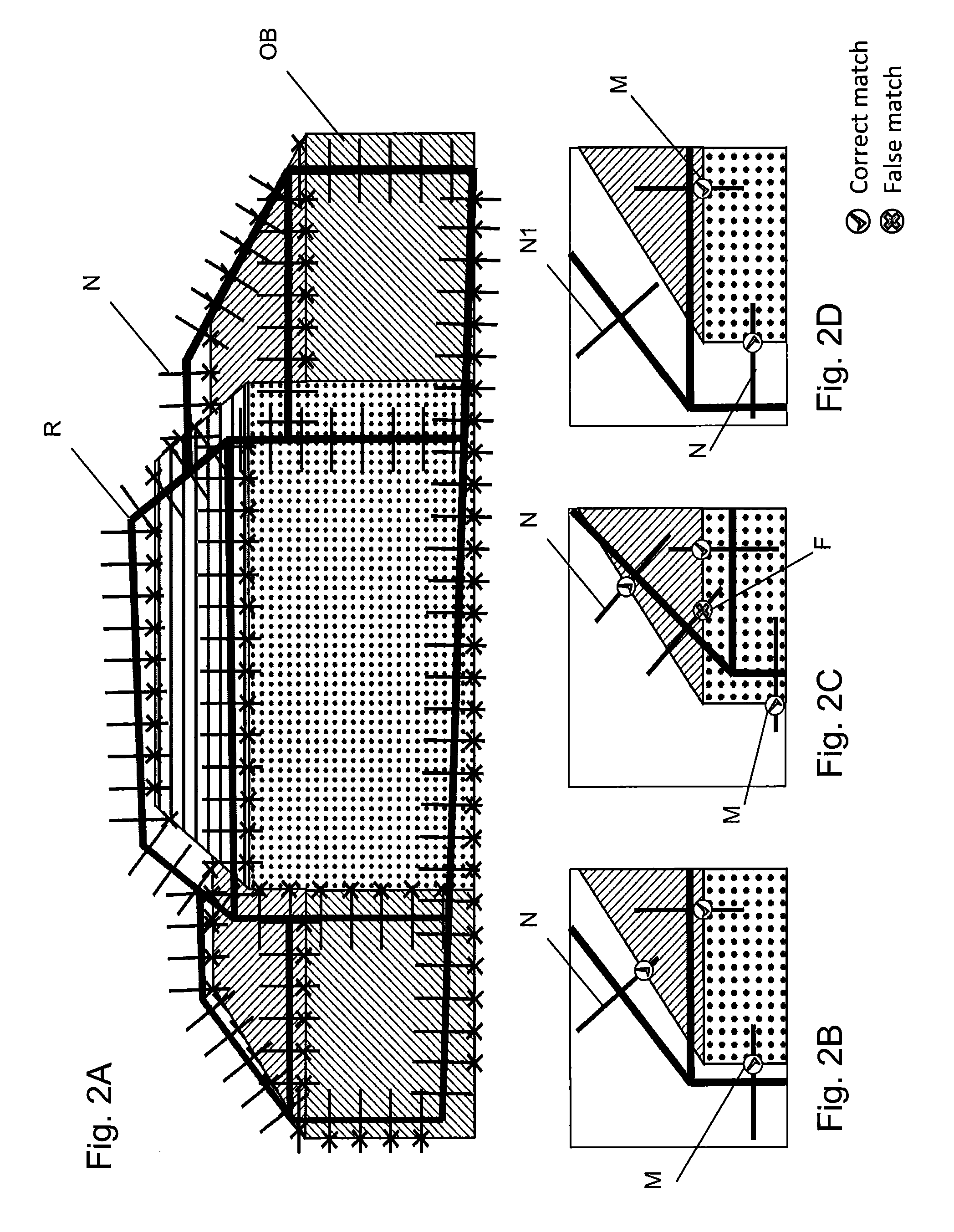
False correspondences can result from but is not limited to noise in the image, occlusion of the object in the image, undersized search range or false choice of the correspondences due to multiple reasonable matching candidates within the used description space for comparison.
In summary, existing approaches for vision-based localization are not robust when the localization is performed with respect to a complex object within a complex scene, i.e. they generally fail when localizing a camera attached to mobile device in an outdoor environment.
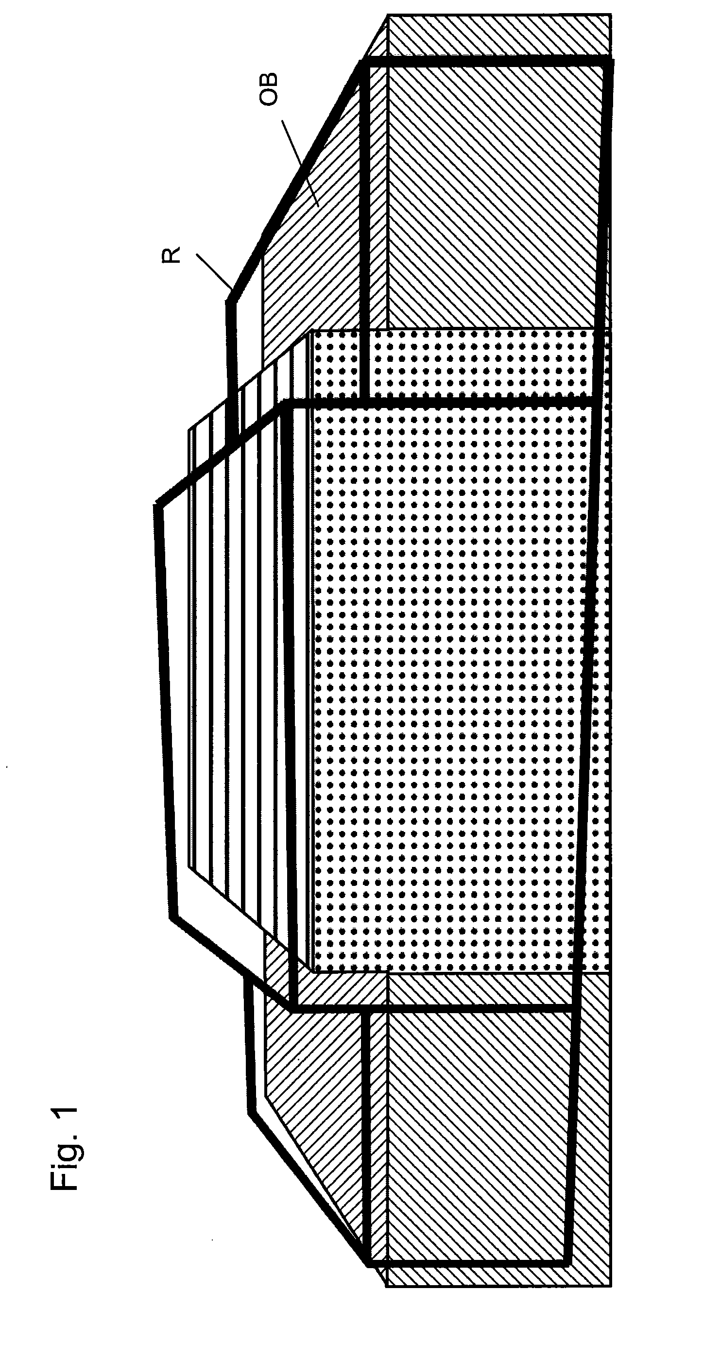
For instance, and more practically, state-of-the-art methods do not solve the problem of localizing a camera with respect to a building façade with known model and the appearance of which has partly changed (e.g. due to open / closed windows / doors, different painting of part of it, changed trees structure in its neighborhood over the seasons) since the registration based on visual data fails as it falls into incorrect local minima during the alignment algorithm.

Method used


Image

  • Method of determining a position and orientation of a device associated with a capturing device for capturing at least one image
  • Method of determining a position and orientation of a device associated with a capturing device for capturing at least one image
  • Method of determining a position and orientation of a device associated with a capturing device for capturing at least one image

Examples


Embodiment Construction

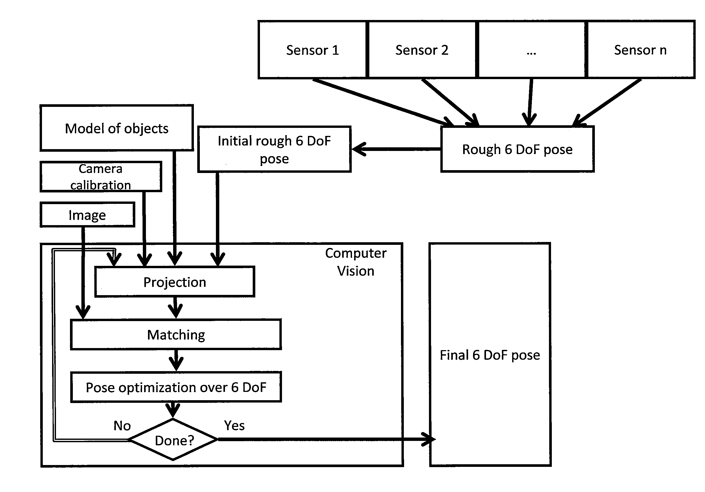
[0070]In the following, aspects of the invention will be explained in more detail in connection with the drawings. In this regard, FIG. 7 shows a flow chart diagram of a process for determining position and orientation of a camera according to state of the art. Particularly, FIG. 7A shows a state of the art method with usage of vision-based localization with using different sensors data for computing an initial pose for final pose estimation, like in Karlekar. FIG. 7B shows a state of the art method with usage of vision-based localization with using different sensors data for sensor fusion like in Reitmayr. As these methods are well known in the art, as evident from the cited references, any further explanation of the methods are not set out in detail herein for reasons of brevity.

[0071]FIG. 8 shows a flow chart diagram of a process for determining position and orientation of a camera according to an embodiment of the invention. Particularly, FIG. 8A shows an embodiment of an integr...


PUM


Abstract

A method of determining a position and orientation of a device is provided. The position and orientation of the device is determined based on multiple degrees of freedom (DoF) and the device is associated with a capturing device for capturing at least one image is provided. The method includes: capturing at least one image of a real object with the capturing device, and providing a coordinate system in relation to the object; providing an estimation of intrinsic parameters of the capturing device; providing pose data to compute first and second DoFs in the coordinate system, with each DoF having a confidence degree; determining an initial pose of the device; performing a pose estimation process, and calculating in the pose estimation process an estimation of the DoFs having a second confidence degree; and determining a position and orientation of the device.

Description

[0001]This application is entitled to the benefit of, and incorporates by reference essential subject matter disclosed in PCT Application No. PCT / EP2012 / 069075 filed on Sep. 27, 2012.BACKGROUND OF THE INVENTION[0002]1. Technical Field[0003]The present invention relates to a method of determining a position and orientation of a device, wherein the position and orientation is determined based on multiple degrees of freedom and the device is associated with a capturing device for capturing at least one image. The invention also relates to a computer program product comprising software code sections for performing the method.[0004]2. Background Information[0005]Localization of a moving capturing device, such as a camera, or a moving device equipped with a capturing device, such as a camera, with respect to objects in a coordinate system attached to the objects (defining a reference origin and a reference orientation of the axes of the objects) is an important task in the field of comput...

Claims


Application Information

Patent Timeline
IPC IPC(8): G06T7/00G06K9/52H04N5/232H04N7/18G06K9/62
CPCG06T7/0042H04N7/18G06K9/52H04N5/23293G06K9/6201G06T7/75G06T7/251G01S5/0247G01S5/163G01S19/53G06T2207/30244G06T2207/20101G06T2207/20036G06V10/242H04N23/631H04N23/635H04N23/80G06T7/73G06F18/22G06T5/00H04N17/002G06T7/80G06T7/33G06T7/70
Inventor LANGER, MARIONMEIER, PETERBENHIMANE, SELIM
Owner APPLE INC
Learn More