
Hydraulic control system for vehicle

a control system and hydraulic technology, applied in the direction of machines/engines, engine starters, transportation and packaging, etc., can solve the problems of inability to smoothly return the hydraulic pressure to the forward clutch, the drive position cannot be smoothly shifted from the d position to the n position, and the inability to actuate the hydraulic pressure of the forward clutch, etc., to achieve the effect of quick disengagement, and improving the hydraulic response of the clutch devi

Inactive Publication Date: 2015-08-20
TOYOTA JIDOSHA KK
View PDF5 Cites 4 Cited by
  • Summary
  • Abstract
  • Description
  • Claims
  • Application Information

AI Technical Summary

Benefits of technology

The present invention relates to a hydraulic control system for vehicles. The technical effects of the invention include improving the hydraulic response of the clutch device by delivering fluid to the clutch device through two delivery lines, even when the engine is stopped automatically or restarted. The flow rate of fluid is increased through the second passage to actuate the clutch device, and the delivery line between the hydraulic source and the clutch device is established smoothly without interrupting the connection. Additionally, the invention allows for quicker engagement and disengagement of the clutch device, regardless of the engine's status.

Problems solved by technology

That is, the pump is also stopped when restarting the stopping engine and hence the hydraulic pressure is unavailable to actuate the clutch.
According to the teachings of JP-A-2010-151229, however, the hydraulic pressure delivered to the forward clutch may not be returned to the accumulator smoothly.
However, the drive position would not be shifted smoothly from the D position to the N position if it takes too long to depressurize the forward clutch.
However, by contrast, it may take time to deliver the oil from the accumulator to the forward clutch to bring the forward clutch into engagement.
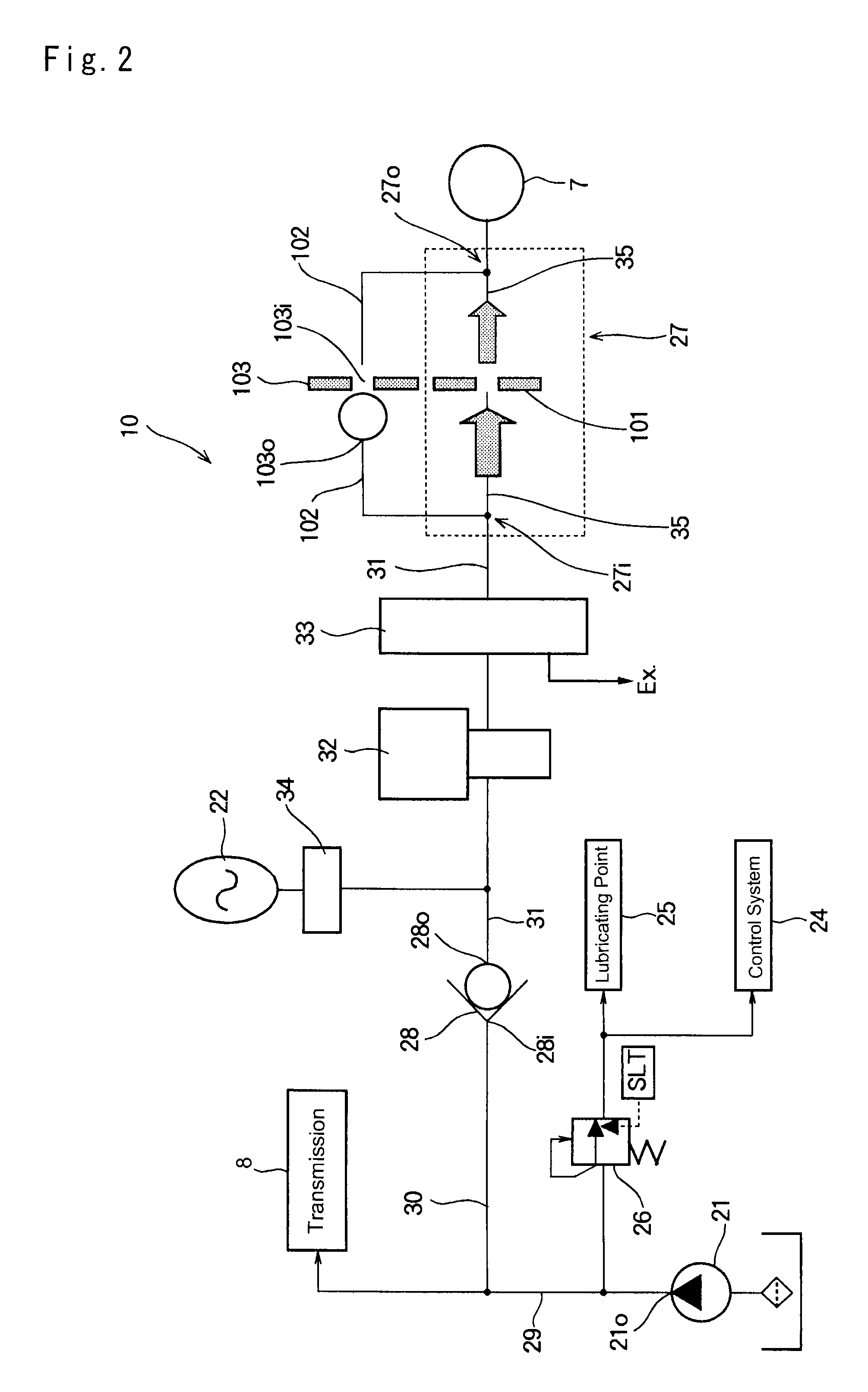
However, if the orifice is diametrically expanded to improve hydraulic response, vibrations and pulses of the oil caused by the solenoid valve would not be suppressed by the orifice and would propagate to the forward clutch.

Method used


Image

  • Hydraulic control system for vehicle
  • Hydraulic control system for vehicle
  • Hydraulic control system for vehicle

Examples


first example

[0052]According to the first example illustrated in FIG. 3, the hydraulic circuit 27 is comprised of a passage 37 on which an orifice 36 is formed, a passage 39 on which an orifice 38 is formed, and a change valve 40 adapted to selectively provide a connection between the passage 37 and the passage 31 and between the passage and the passage 31. Those passages 37 and 39 are arranged parallel to each other between the passage 31 on which the clutch control valve 32 and the manual valve 33 are disposed and the passage 35 connected to the clutch device 7, and both leading ends of the passages 37 and 39 of the clutch device 7 side are connected to the passage 35. Leading ends of the passages 37 and 39 of the other side are connected to the passage 31 through the change valve 40.

[0053]A structure of the orifice 36 is similar to that of the aforementioned conventional orifice 101, and a diameter of the orifice 36 is optimized to suppress hydraulic vibrations and pulses caused by the clutch...

second example

[0059]According to the second example illustrated in FIG. 4, the hydraulic circuit 27 is comprised of a passage 42 on which an orifice 41 is formed, and a passage 45 on which an on-off valve 43 is disposed and an orifice 44 is formed. Those passages 42 and 45 are arranged parallel to each other between the passage 31 on which the clutch control valve 32 and the manual valve 33 are disposed and the passage 35 connected to the clutch device 7, and both leading ends of the passages 42 and 45 of the manual valve 33 side are connected to the passage 31. Leading ends of the passages 42 and 45 of the clutch device 7 side are connected to the passage 35.

[0060]A structure of the orifice 41 is also similar to that of the aforementioned conventional orifice 101, and a diameter of the orifice 41 is optimized to suppress hydraulic vibrations and pulses caused by the clutch control valve 32. On the other hand, a diameter of the orifice 44 is optimized to ensure sufficient flow rate of the fluid f...

third example

[0067]According to the third example illustrated in FIG. 5, the hydraulic circuit 27 is comprised of a passage 47 on which an orifice 46 is formed, and a passage 50 on which a solenoid valve 48 is disposed and an orifice 49 is formed. Those passages 47 and 50 are arranged parallel to each other between the passage 31 on which the clutch control valve 32 and the manual valve 33 are disposed and the passage 35 connected to the clutch device 7, and both leading ends of the passages 47 and 50 of the manual valve 33 side are connected to the passage 31. Leading ends of the passages 47 and 50 of the clutch device 7 side are connected to the passage 35. In addition, a pressure gauge 51 is disposed on the passage 35 to measure pressure of the fluid to engage the clutch device 7.

[0068]A structure of the orifice 46 is also similar to that of the aforementioned conventional orifice 101, and a diameter of the orifice 46 is optimized to suppress hydraulic vibrations and pulses caused by the clut...


PUM


Abstract

A hydraulic control system for vehicle includes: an engine; an oil pump driven by the engine; a clutch device brought into engagement to enable power transmission between the engine and drive wheels by delivering a pressurized fluid thereto, and brought into disengagement to interrupt the power transmission between the engine and the drive wheels by discharging the fluid therefrom; and an accumulator storing the fluid delivered to the clutch device. The hydraulic control system is configured to control the hydraulic pressure applied to the clutch device, to stop the engine while bringing the clutch device into disengagement upon satisfaction of a predetermined stopping condition, and to restart the engine while bringing the clutch device into engagement upon satisfaction of a predetermined restarting condition. In the hydraulic control system, a hydraulic circuit increases flow rate of the fluid flowing between the accumulator and the clutch device when the engine is stopped.

Description

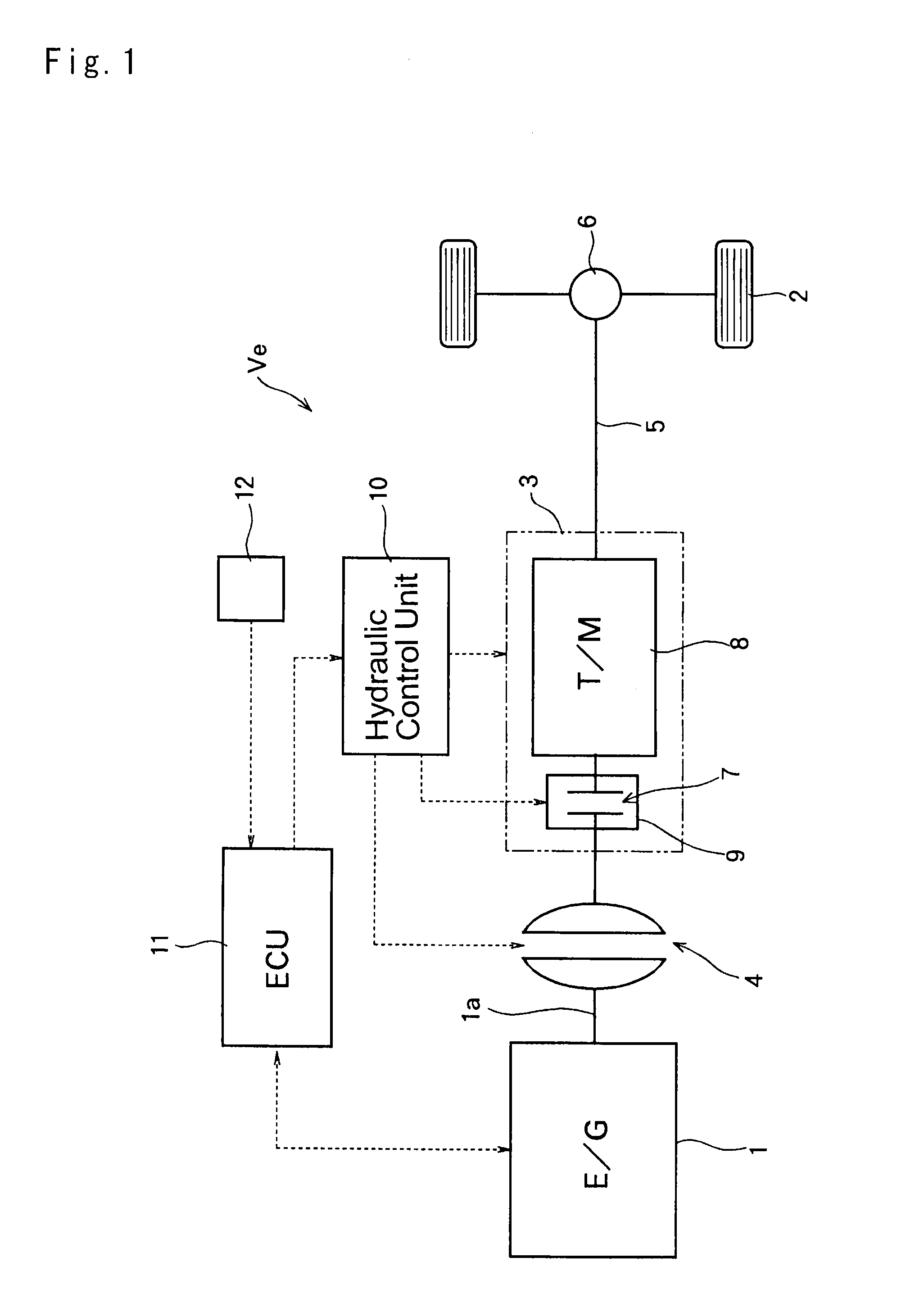
TECHNICAL FIELD[0001]The present invention relates generally to a hydraulic control system for automatically stopping and starting an engine of a vehicle in operation to reduce fuel consumption and emissions. More particularly, the present invention relates to a hydraulic control system configured to control actuation of a clutch selectively connecting the engine to drive wheels when stopping and starting the engine.BACKGROUND ART[0002]In recent years, so-called “stop and start” control (abbreviated as “S & S” control hereinafter) of an engine has been adapted to reduce fuel consumption and emissions of automobiles. Under the S & S control, the engine is automatically stopped and restarted upon satisfaction of predetermined conditions. For example, the engine is stopped when an accelerator pedal is returned, and restarted when a brake pedal is returned.[0003]However, when stopping or restarting the engine by the S & S control, an output torque of the engine would be varied significa...

Claims


Application Information

Patent Timeline
Patent Type & Authority Applications(United States)
IPC IPC(8): B60W30/192B60W10/06B60W10/02B60W30/20F16D48/02
CPCB60W30/192B60W30/20F16D48/02B60W10/02F16D2048/0257B60W2030/203B60W2030/206F16D2048/0203F16D2048/0221B60W10/06F16H61/0025F16H2061/0034F16H2312/14
Inventor MORINO, TAKUROMORIYAMA, SHUJIITO, YOSHIO
Owner TOYOTA JIDOSHA KK
Learn More