
Bone fixing system

a technology for fixing systems and bones, applied in the field of bone fixing systems, can solve the problems of paralysis of patients, damage or lack of purchase, and difficulty in using hooks, and achieve the effect of convenient handling

Active Publication Date: 2015-08-13
LDR MEDICAL SAS
View PDF0 Cites 18 Cited by
  • Summary
  • Abstract
  • Description
  • Claims
  • Application Information

AI Technical Summary

Benefits of technology

The patent text describes a bone fixing system that is safer, easier to handle, and provides dynamic stabilization. The system has a compact design and is easy to operate with a tool being passed through the first internal passage. The method is effective for holding two or more vertebrae in correct position relative to each other. The elongate member has a certain amount of elasticity, which allows limited amount of relative movement between the bone and the rod while providing a stabilizing effect.

Problems solved by technology

However, using hooks can be difficult because their use increases the risk that the physician (or other operative) might contact and potentially damage the spinal cord that extends along the vertebral foramen (which can result in paralysis of the patient).
However, the screws are inserted into the pedicles of the vertebrae, which in some cases are small or have deteriorated and can be damaged or do not provide sufficient purchase to permanently hold the screw.
Such a system does not give complete satisfaction because it may be difficult to handle for the physician (or other operative).

Method used


Image

  • Bone fixing system
  • Bone fixing system
  • Bone fixing system

Examples


Embodiment Construction

[0057]In the following detailed description, it is referred to the accompanying drawings showing several examples of bone fixing systems according to the present disclosure. It is intended that these examples be considered as illustrative but not limiting, the scope of the invention being given by the accompanying claims.

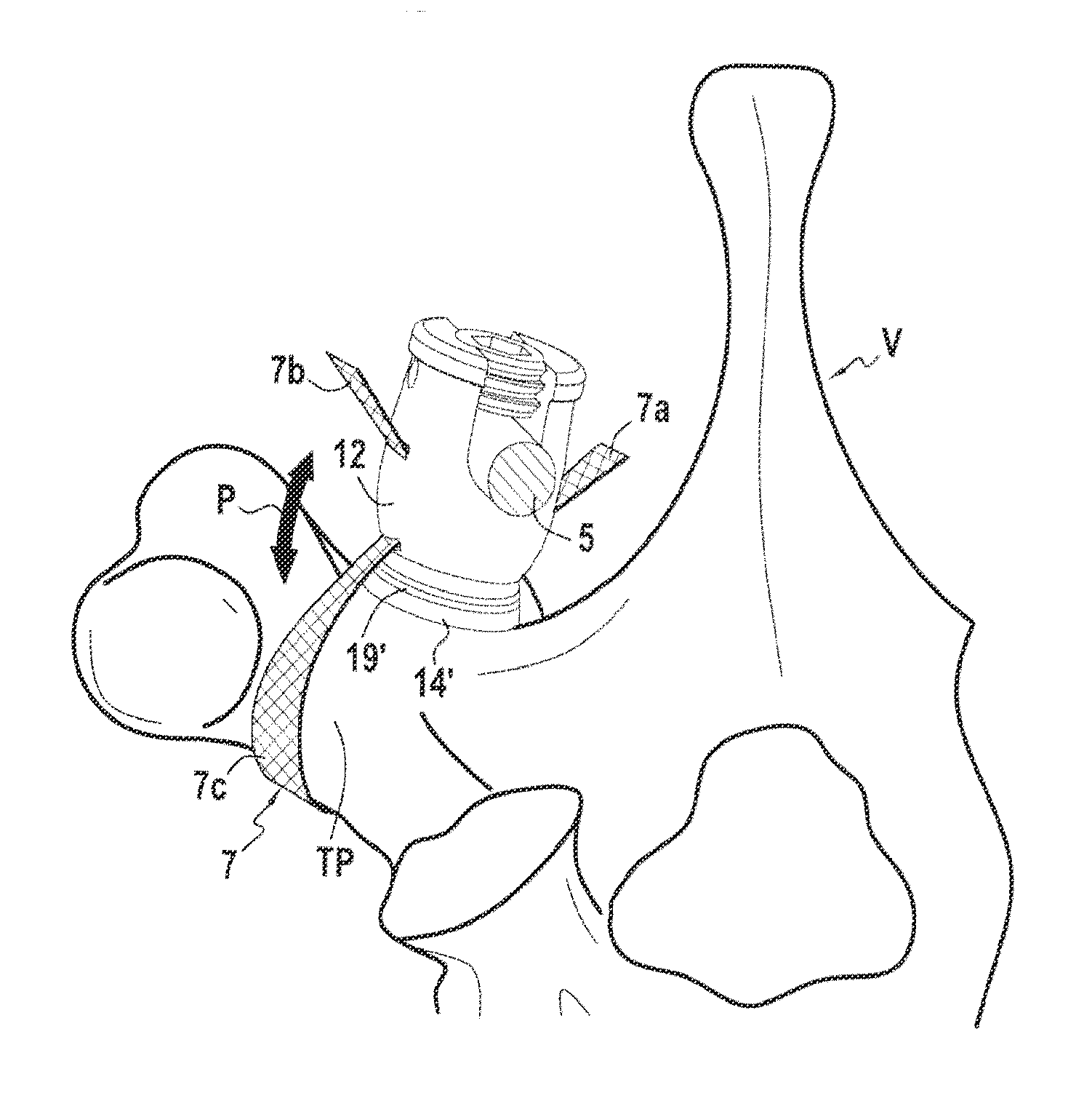
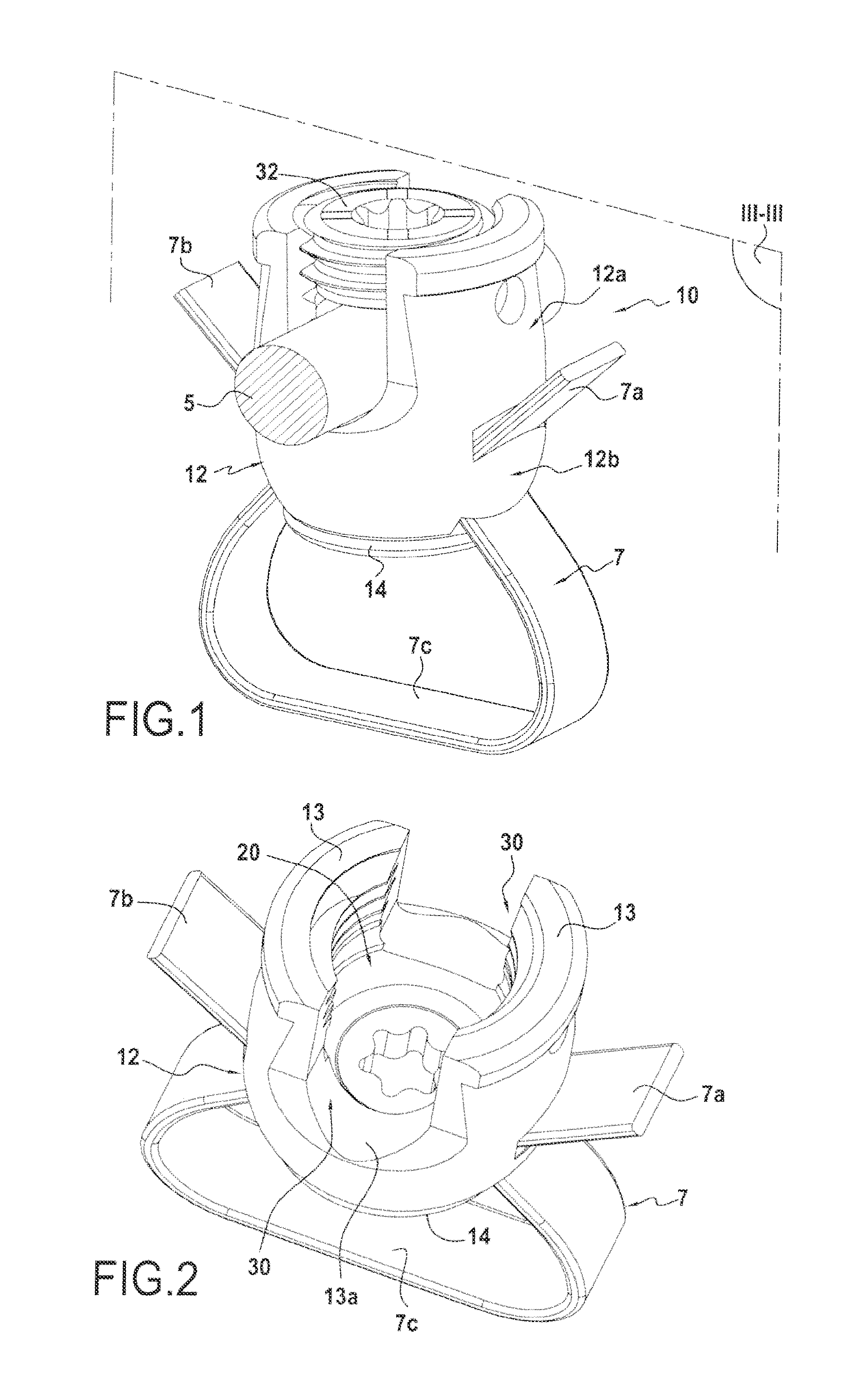
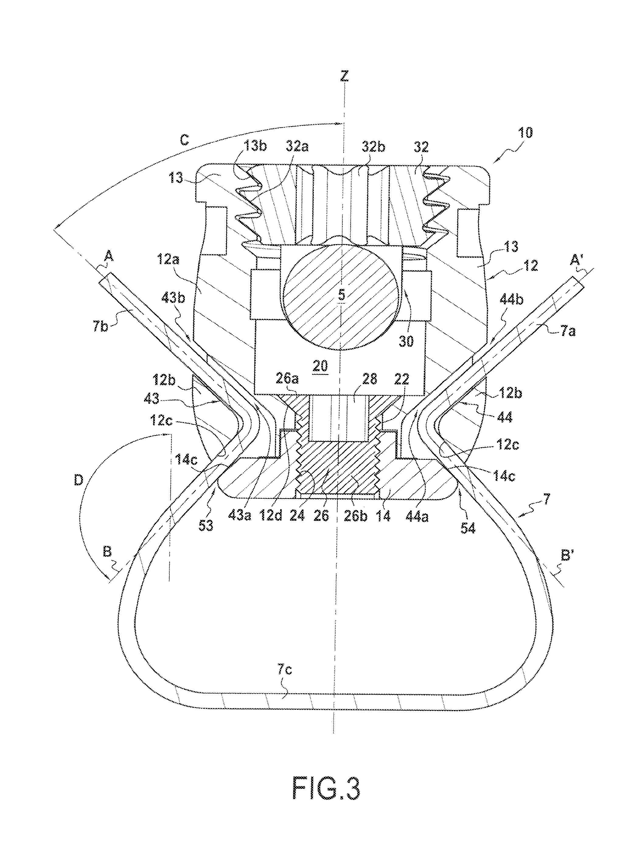
[0058]An example of bone fixing system is shown on FIGS. 1 to 3. The bone fixing system 10 is for fixing a rod 5 (a portion of which is shown in FIGS. 1, 3 and 15) to a bone (see FIG. 15). The bone may be, for instance, a lamina of a vertebra or a transverse process TP of a vertebra V, as shown in FIG. 15.

[0059]The bone fixing system 10 comprises

[0060]a conformable elongate member 7, such as a ligature, having a first free end portion 7a, a second free end portion 7b, and an intermediate portion 7c therebetween, said intermediate portion 7c being adapted to surround the bone (e.g. the transverse process TP);

[0061]a main body 12;

[0062]first fastening device or means ...


PUM


Abstract

This disclosure provides a system for securing a bone to a rod, the system comprising a ligature, a body, and two fasteners. The ligature has two free ends and an intermediate portion therebetween, the intermediate portion being configured to engage a bone. A portion of a rod can be fastened to the body using one of the fasteners. The ligature can be fastened to the body using another one of the fasteners. The two fasteners are distinct from one another and are adapted to fasten two free end portions of the ligature to the body independently from fastening the portion of the rod to the body.

Description

CROSS-REFERENCE TO RELATED APPLICATIONS[0001]This application is a continuation of U.S. patent application Ser. No. 13 / 384,180, filed Jan. 13, 2012, which is a U.S. national stage application, which claims the benefit of International Application No. PCT / EP2010 / 061085, filed Jul. 30, 2010, entitled “BONE FIXING SYSTEM,” which claims priority from European Patent Application No. EP 09305720.6, filed Jul. 31, 2009. All applications referenced herein are hereby incorporated by reference in their entireties.FIELD OF THE INVENTION[0002]The present disclosure relates generally to systems and methods for fixing a bone to a rod. Such systems and methods may be helpful for holding together a bone and a rod in a desired configuration or in a particular relative position. In particular, the bone may be a transverse process or a lamina of a vertebra.BACKGROUND OF THE INVENTION[0003]One field of application for the invention is fixing bones in a desired position, for example to aid in healing of...

Claims


Application Information

Patent Timeline
Patent Type & Authority Applications(United States)
IPC IPC(8): A61B17/70
CPCA61B17/7032A61B17/7001A61B17/7062A61B17/8028A61B17/842A61B17/7053A61B17/82A61B17/70A61B17/7026A61B17/7022
Inventor LARROQUE-LAHITETTE, GILLES
Owner LDR MEDICAL SAS
Learn More