Moving floor system

a moving floor and conveying system technology, applied in mechanical conveyors, conveyor parts, packaging, etc., can solve the problems of tools and other equipment needed, and achieve the effect of reducing the footprint of the moving floor system

Active Publication Date: 2015-08-06
PFLOW INDS
View PDF16 Cites 10 Cited by
  • Summary
  • Abstract
  • Description
  • Claims
  • Application Information

AI Technical Summary

Benefits of technology

[0004]The moving floor system of the present disclosure is created within a pit formed in the floor of a factory or plant. The moving floor system includes the moving work surface at an upper, first level a...

Problems solved by technology

During this assembly, the assembly line workers must move along with the product, which...

Method used


Image

  • Moving floor system
  • Moving floor system
  • Moving floor system

Examples


Embodiment Construction

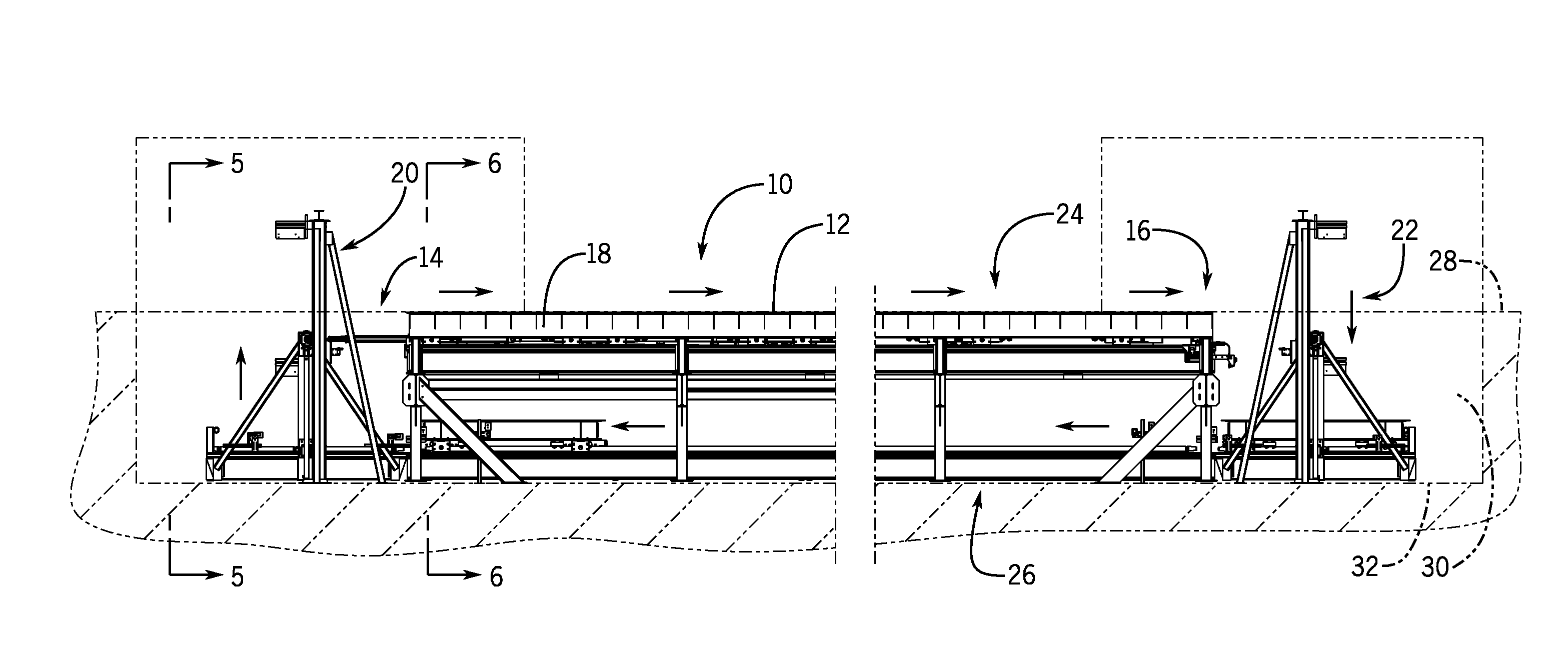
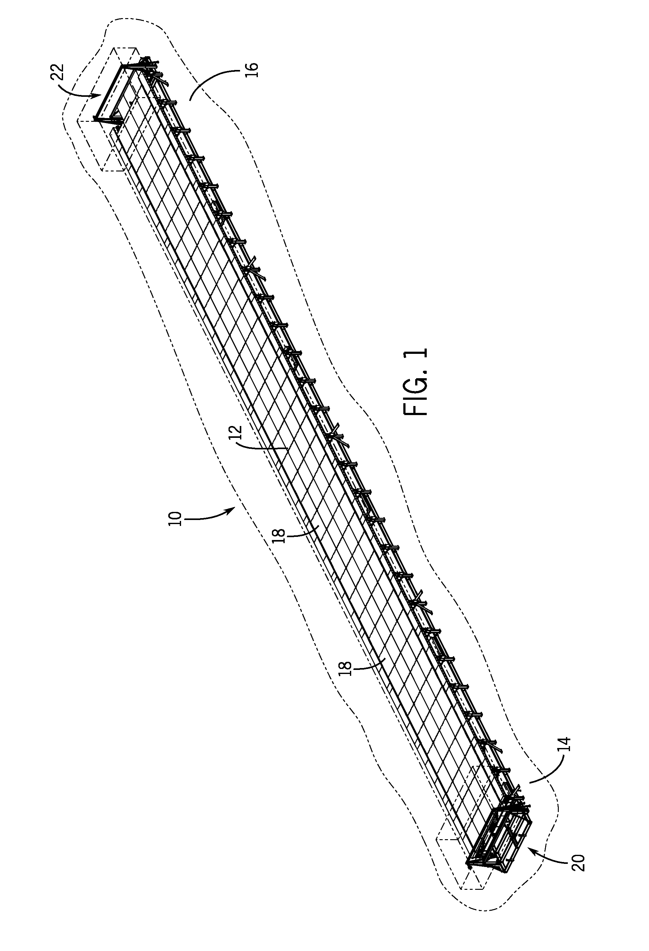
[0032]FIG. 1 illustrates the moving floor system 10 of the present disclosure. The moving floor system 10 shown in FIG. 1 creates a moving work surface 12 that is able to move large products, such as farm implements, trucks or other similar products being assembled along an assembly line from a first, upstream end 14 to a second, downstream end 16. In the embodiment shown in FIG. 1, the moving floor system defines a 350′ long by 25′ wide work surface 12. The work surface, in the embodiment illustrated, moves at a selected constant velocity of approximately 3.2′ fpm or less. As will be described in detail below, the speed of the work surface 12 can be varied depending on the specific application and could be any speed reasonable for the working environment.

[0033]The work surface 12 is formed by a series of adjacent carts 18 that are each 25′ wide and 10′ long and are moved from the upstream end 14 to the downstream end 16 as an assembled stack. At the speed indicated, each of the ind...


PUM


Abstract

A moving floor system that includes a moving work surface to move work products from an upstream end to a downstream end. The moving work surface is formed from a plurality of individual carts joined to each other. The stack of carts is moved along upper support rails located at an upper level. When each individual cart reaches the downstream end, a downstream lift conveyor moves the individual cart from the upper level to a lower level. When at the lower level, each individual cart is returned from the downstream end to the upstream end. When each individual cart reaches the upstream end, an upstream lift conveyor returns the individual carts from the lower level to the upper level. An upper drive mechanism provides the motive force to move the stack of carts along the upper level at the working speed.

Description

CROSS-REFERENCE TO RELATED APPLICATION[0001]The present application is based on and claims priority to U.S. Provisional Patent Application Ser. No. 61 / 935,124 filed Feb. 3, 2014, the disclosure of which is incorporated herein by reference.BACKGROUND[0002]The present disclosure relates to a moving floor conveying system for moving large products from a first end of an assembly line to a second end of the assembly line. The moving floor conveying system supports and moves the products along the assembly line such that various steps of assembly can be performed while the product is moving along with the moving work surface.[0003]Presently, when large products, such as farm implements, trucks or airplanes, are assembled, the product is typically moved along an assembly line where different stages of the assembly take place. In such situations, the large product is moved along the assembly line and various different assembly line workers work on the product during this movement. During t...

Claims


Application Information

Patent Timeline
IPC IPC(8): B65G35/08B65G47/57
CPCB65G47/57B65G35/08B65G35/06B65G37/02
Inventor WEBSTER, MARKKONOPACKI, DAVIDREILLY, MICHAEL
Owner PFLOW INDS
Why Eureka
Try Eureka