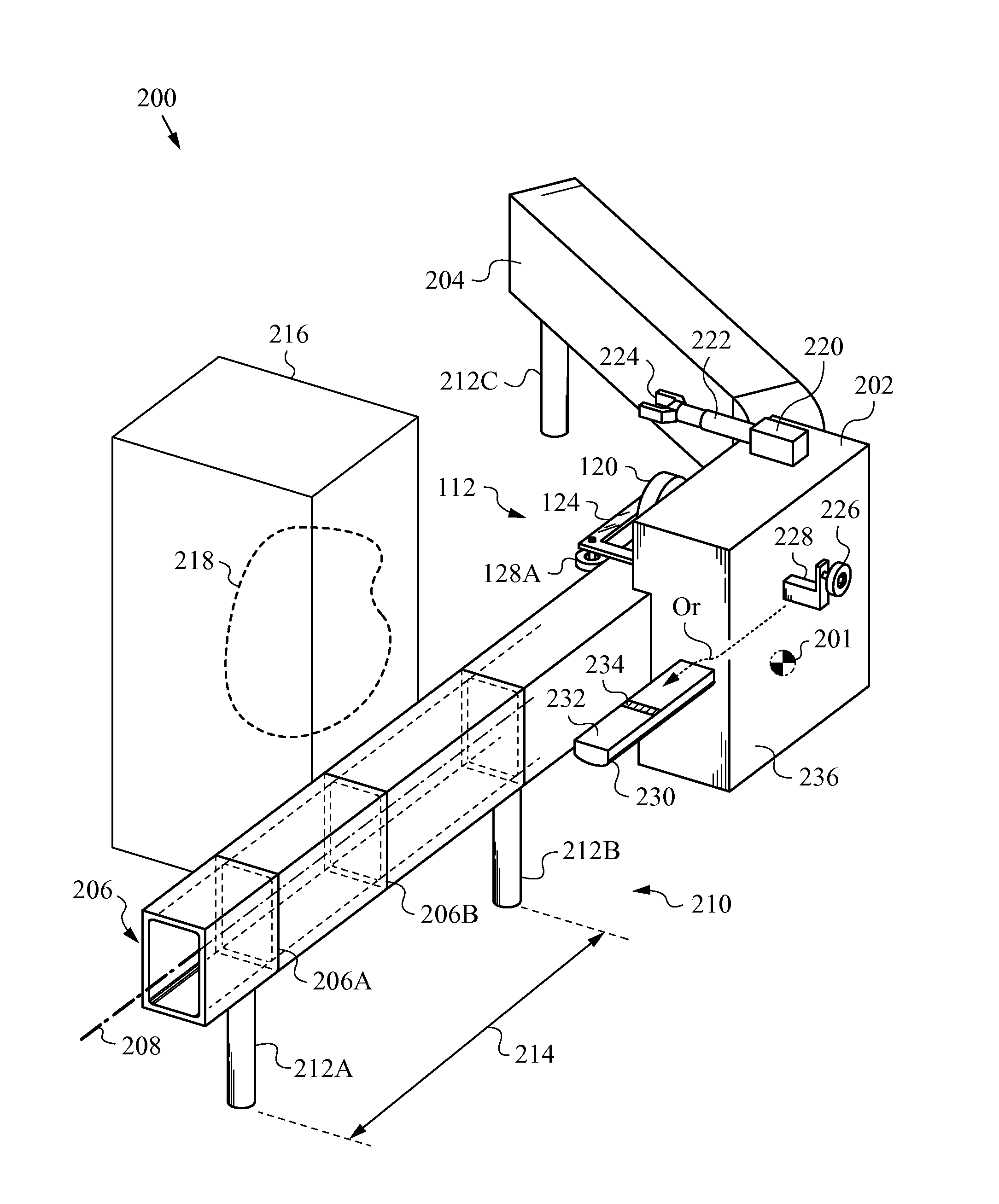
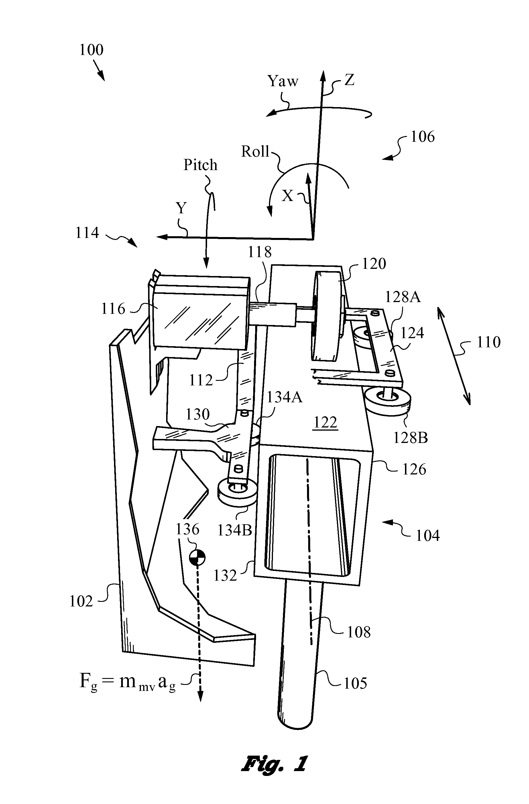
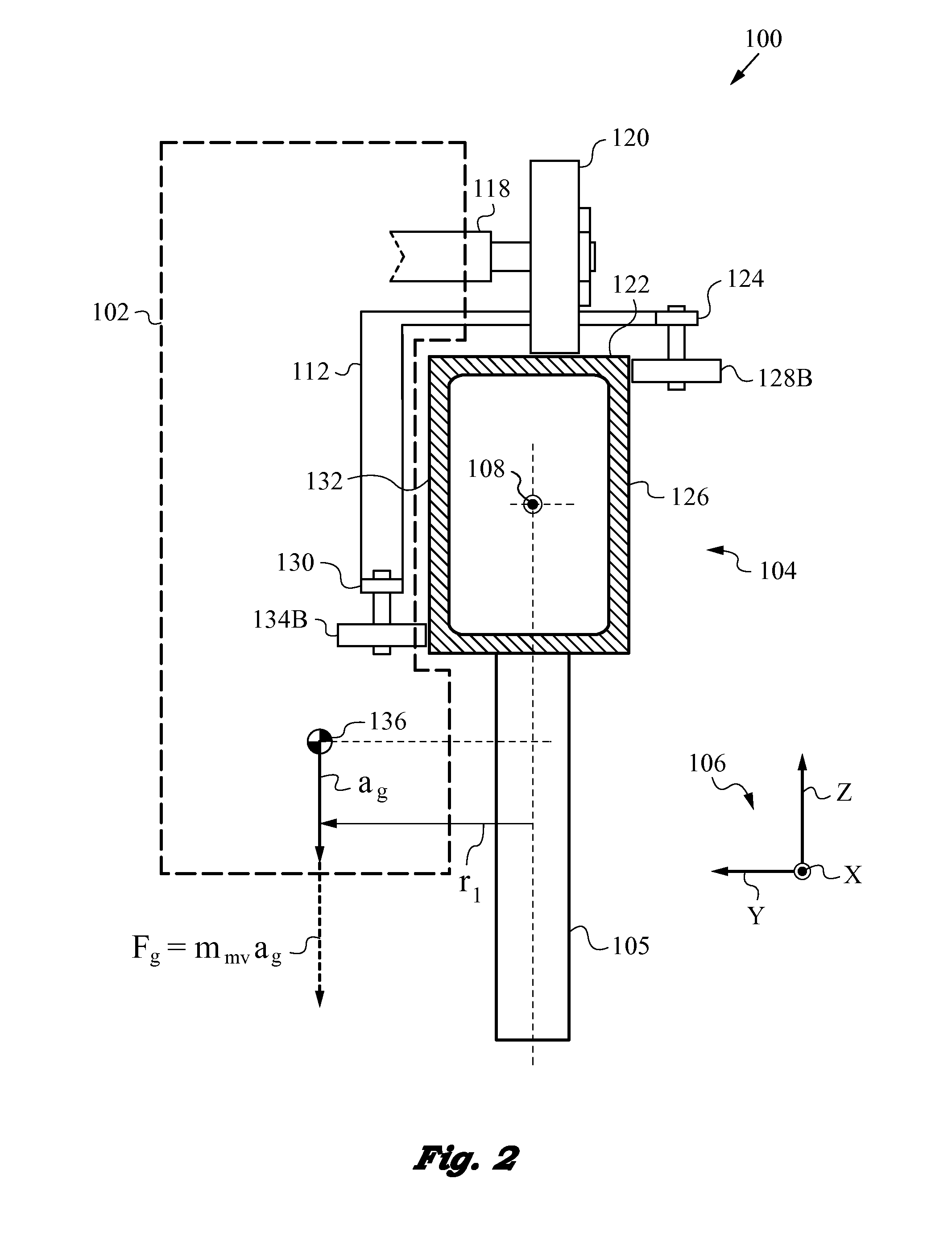
Monorail vehicle apparatus with trucks designed to accommodate movement along curved rail sections
a vehicle and rail technology, applied in the direction of wheel axle self-adjustment, transportation and packaging, roads, etc., can solve the problems of not teaching control forces, not supporting accurate trolley localization on a non-featured rail, and more challenging constraining of rotation about the longitudinal direction or about the rail. , to achieve the effect of accurate constraint of roll attitude and lateral translation
- Summary
- Abstract
- Description
- Claims
- Application Information
AI Technical Summary
Benefits of technology
Problems solved by technology
Method used
Image

Examples
Embodiment Construction
[0054]The figures and the following description relate to preferred embodiments of the present invention by way of illustration only. It should be noted that alternative embodiments of the structures and methods disclosed herein will be readily recognized as viable options that can be employed without departing from the principles of the claimed invention.
[0055]Reference will now be made to several embodiments of the present invention, examples of which are illustrated in the accompanying figures. Similar or like reference numbers are used to indicate similar or like functionality wherever practicable. The figures depict embodiments of the present invention for purposes of illustration only. One skilled in the art will readily recognize from the following description that alternative embodiments of the structures and methods illustrated herein may be employed without departing from the principles of the invention described herein.
[0056]The present invention will be best understood b...
PUM
 Abstract
Description
Claims
Application Information
 - R&D
- Intellectual Property
- Life Sciences
- Materials
- Tech Scout
- Unparalleled Data Quality
- Higher Quality Content
- 60% Fewer Hallucinations
Browse by: Latest US Patents, China's latest patents, Technical Efficacy Thesaurus, Application Domain, Technology Topic, Popular Technical Reports.
© 2025 PatSnap. All rights reserved.Legal|Privacy policy|Modern Slavery Act Transparency Statement|Sitemap|About US| Contact US: help@patsnap.com