
Electronically Controlled Suspension System, Method for Controlling a Suspension System and Computer Program

a suspension system and electronic control technology, applied in the field of bicycles, can solve the problems of limited apparatus operational reliability, limited elastic force adaptability, and only rudimentary adaptation to different riding conditions, and achieve the effect of improving operational reliability

Active Publication Date: 2015-07-16
GUSTAV MAGENWIRTH GMBH & CO KG
View PDF10 Cites 109 Cited by
  • Summary
  • Abstract
  • Description
  • Claims
  • Application Information

AI Technical Summary

Benefits of technology

The patent describes a new electric chassis for bicycles that solves problems with previous devices by improving reliability and offering more adjusting options. It also introduces an electronically controlled suspension system that can be attached to the front, rear, or seat post / stating tube, raising rider comfort and improving grip and safety on the bike. Additionally, it discusses the use of an electric motor in bicycles to make them faster and easier to manage steer.

Problems solved by technology

This known apparatus has a drawback in that the cable connections can corrode or tear off when riding the bicycle off-road, which limits the operational reliability of the apparatus.
Although it is possible by this known apparatus to adapt the damping, it is not possible to adapt the elastic force and, therefore, an adaptation to different riding conditions is only rudimentarily possible.

Method used


Image

  • Electronically Controlled Suspension System, Method for Controlling a Suspension System and Computer Program
  • Electronically Controlled Suspension System, Method for Controlling a Suspension System and Computer Program
  • Electronically Controlled Suspension System, Method for Controlling a Suspension System and Computer Program

Examples


Embodiment Construction

[0083]As required, detailed embodiments of the systems and methods are disclosed herein; however, it is to be understood that the disclosed embodiments are merely exemplary of the systems and methods, which can be embodied in various forms. Therefore, specific structural and functional details disclosed herein are not to be interpreted as limiting, but merely as a basis for the claims and as a representative basis for teaching one skilled in the art to variously employ the systems and methods in virtually any appropriately detailed structure. Further, the terms and phrases used herein are not intended to be limiting; but rather, to provide an understandable description of the systems and methods. While the specification concludes with claims defining the features of the systems and methods that are regarded as novel, it is believed that the systems and methods will be better understood from a consideration of the following description in conjunction with the drawing figures, in whic...


PUM


Abstract

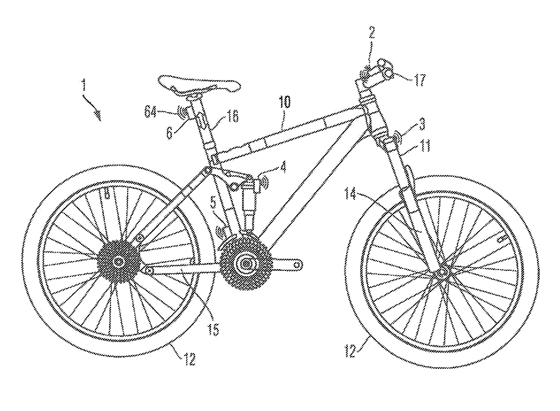
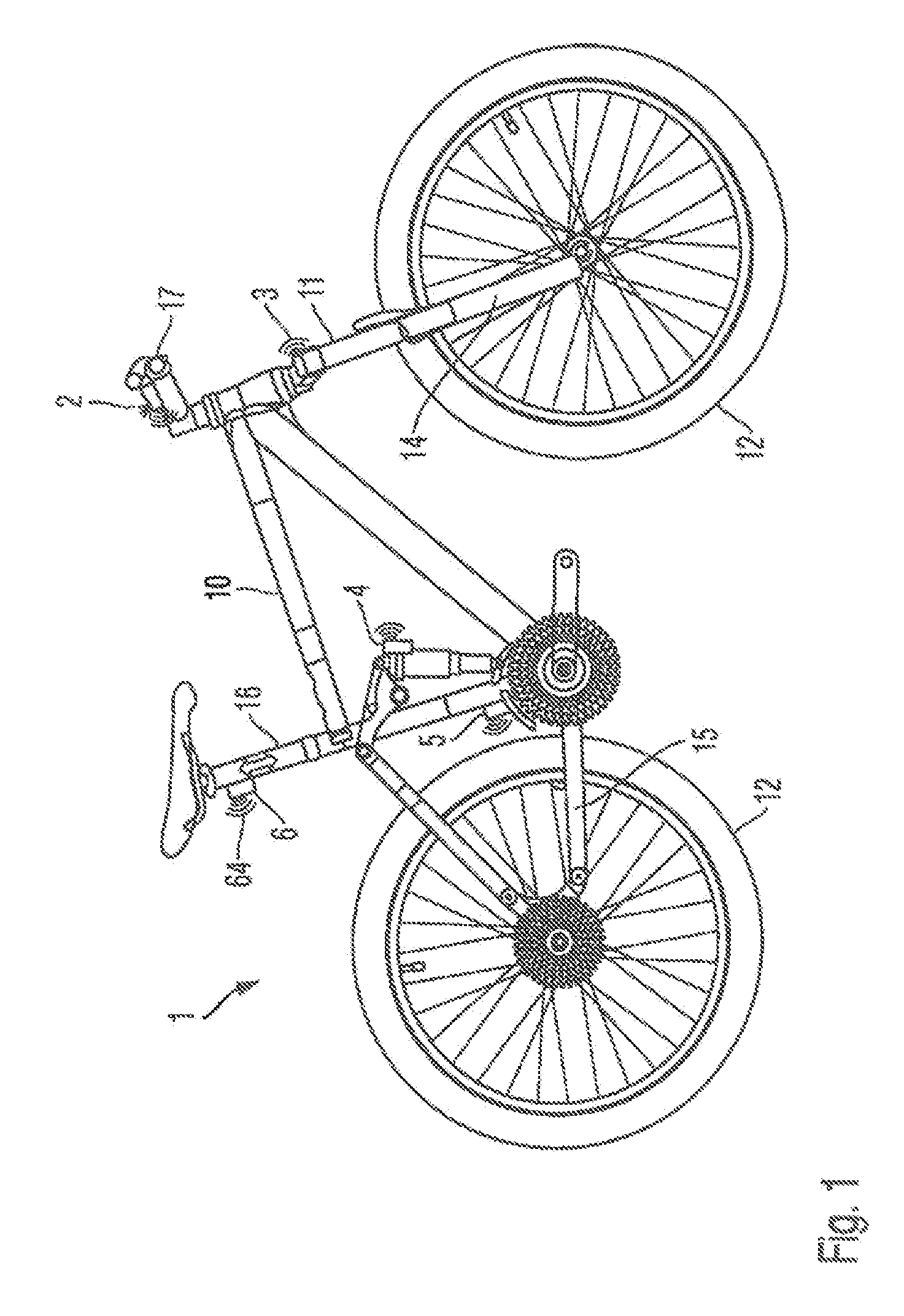
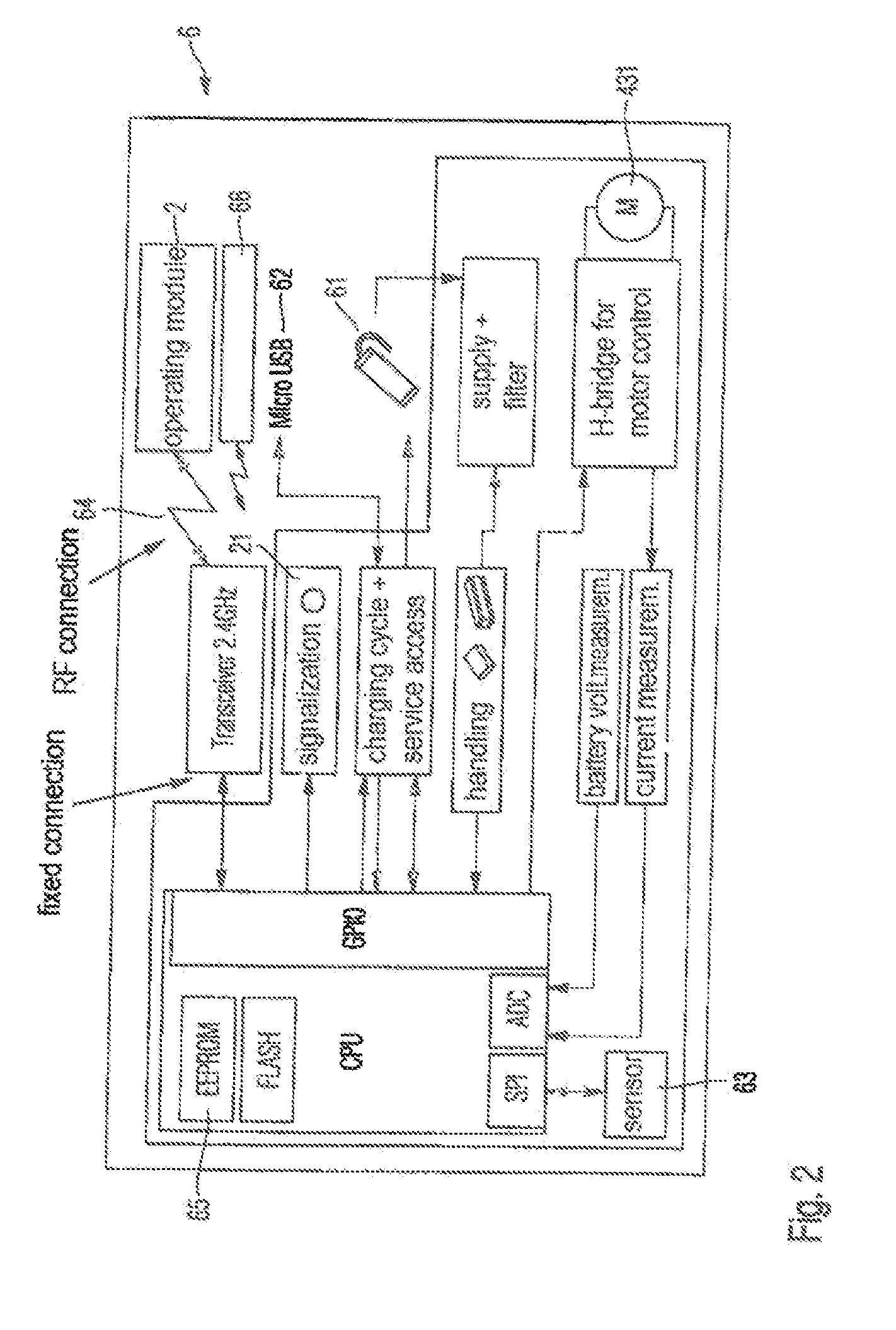
An electronically controlled suspension system for a bicycle includes at least one spring element between first and second parts the bicycle, both parts being movably interconnected. At least one parameter of the spring element is modified. At least one actuator influences the spring element to modify the at least one parameter. An electronic module produces a control signal for the at least one actuator. A control device is influenced by the control signal produced by the electronic module. The control device is connected to at least one of the electronic module and the actuator through a radio signal. A corresponding method controls the suspension system for the bicycle and a computer program executes the method.

Description

CROSS-REFERENCE TO RELATED APPLICATIONS[0001]This is a continuing application, under 35 U.S.C. §120, of copending international application No. PCT / EP2013 / 067286, filed Aug. 20, 2013, which designated the United States and was not published in English; this application also claims the priority, under 35 U.S.C. §119, of German Patent Application Nos. 10 2012 214 867.1, filed Aug. 21, 2012, and 10 2012 215 062.5 filed on Aug. 24, 2012; the prior applications are herewith incorporated by reference in their entirety.STATEMENT REGARDING FEDERALLY SPONSORED RESEARCH OR DEVELOPMENT[0002]Not ApplicableFIELD OF THE INVENTION[0003]The present systems and methods lies in the field of cycles. The present disclosure relates to an electronically controlled suspension system for a bicycle, comprising at least one spring element that is disposed between a first part of the bicycle and a second part of the bicycle, both parts being movably interconnected, wherein at least one parameter of the spring...

Claims


Application Information

Patent Timeline
Patent Type & Authority Applications(United States)
IPC IPC(8): B62K25/20B62K25/08B62J1/06
CPCB62K25/20B62J1/06B62K25/08B62K2207/04B62J2099/0026B62K2025/045B62J2099/002B62K25/10B62K2025/044B62J45/20B62J45/411B62J45/412B62J45/414B62J45/415B62J50/22B62J45/00B62J45/4152
Inventor BUTORA, PETERBEIER, JURGENKUNSTLE, REINERKOLLER, FLORIANKERN, CHRISTOPH
Owner GUSTAV MAGENWIRTH GMBH & CO KG
Learn More