Electronic parking disc

a technology of electronic parking discs and parking timers, which is applied in the field of parking discs, can solve the problems of difficult to reset parking time, difficult to check, and the satellite control of a clock in an electronic parking disc will not be very suited to parking in closed parking facilities without free access to open skies

Active Publication Date: 2015-07-16
BENT NEUBAUER HLDG
View PDF4 Cites 1 Cited by
  • Summary
  • Abstract
  • Description
  • Claims
  • Application Information

AI Technical Summary

Benefits of technology

The patent describes an electronic parking disc that can be used in different vehicles. The display of the disc can be switched based on measured parameters indicating movement of the vehicle, such as minimum acceleration or turning around one or more corners. This prevents cheating with the disc and ensures reliable use by both users and parking administration. The disc can also have a fixed time to indicate the start of parking, making it difficult for users to cheat with the display. The patent also suggests using a combination of signals from an acceleration detector and a gyro meter to switch the display. Overall, the patent provides a technical solution to improve the accuracy and reliability of electronic parking discs.

Problems solved by technology

A substantial drawback may be that it is possible to reset a parking time by simply switching on the ignition of the vehicle and the leave the vehicle again, i.e., the parking time is renewed without moving the vehicle.
Such an action is not allowed according to the common parking rules, but is almost impossible to check.
Thus there may arise a number of contentious issues between traffic wardens and vehicle owners provided with electronic parking discs, as the traffic warden may assert abuse by demonstrating that the car wheels haven't been moved in spite of the parking time having been changed.
However, any satellite control of a clock in an electronic parking disc will not be very suited for parking in closed parking facilities without free access to open sky, i.e., parking in cellars or the lower storeys in high parking buildings where a satellite signal cannot be received.

Method used


Image

  • Electronic parking disc
  • Electronic parking disc
  • Electronic parking disc

Examples


Embodiment Construction

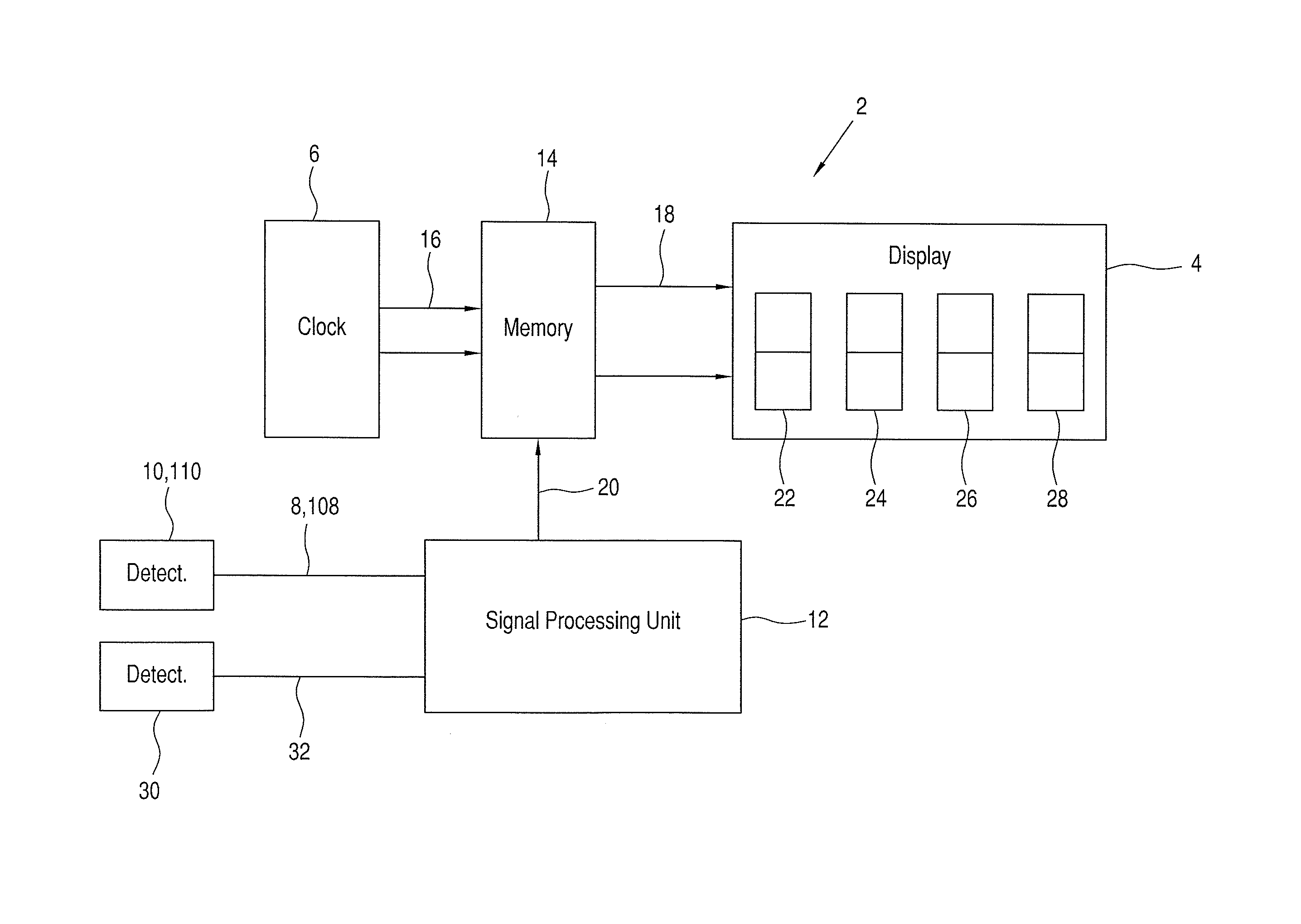
[0025]An electronic parking disc 2 contains a display 4 that communicates with an electronic clock 6, where a signal wire 8 communicates with an first detectors 10 and a second detector in form of a gyro detector 30, which detectors 10, 30 are connected to a signal processing unit 12. An electric connection 20 goes from signal processing unit 12 to a memory unit 14 that receives a time signal over a data bus 16 from the electronic clock 6, and where the memory unit 14 over a data bus 18 transmits a signal to display 4 containing segments 22, 24, 26 and 28.

[0026]The operation of the parking disc on the Figure may be as follows: During normal operation, the electronic clock 6 may deliver a time signal over databus 16, and this signal is forwarded through memory unit 14 over databus 18 to display 4 so that the display shows actual time. A condition for actual display of time may be that the signal wire 20 connecting the electronic control unit 12 with memory unit 14 contains a logical ...


PUM


Abstract

Parking disc for mounting on a vehicle in a location so as to be at least externally visible for indicating a time for initiation of the parking with an electronic display which shows the actual time during normal driving and during parking constantly shows the time of initiation of the parking. The parking disc is designed so that switching the display when resuming driving is effected on the basis of an electric signal from at least one detector that determines an actual relative movement of the vehicle in excess of a minimum value with the electronic parking disc continuing to show a fixed time that indicates initiation of parking until the mentioned detector has determined the minimum value of movement of the vehicle has occur. This value may, e.g., be that the vehicle has moved at least a certain distance from the point at which parking had been initiated.

Description

CROSS REFERENCE TO RELATED APPLICATION[0001]This application is a continuation-in-part of commonly owned, co-pending U.S. patent application Ser. No. 12 / 997,738, filed Dec. 13, 2010, which co-pending application is a §371 of PCT / DK2009 / 050144, filed Jun. 25, 2009.BACKGROUND OF THE INVENTION[0002]1. Field of the Invention[0003]The present invention concerns a parking disc for mounting on a vehicle where the parking disc is placed visible from outside, where the parking disc includes means for at least externally indicating a time for initiation of the parking, where means for indicating the time consists of an electronic display which during normal driving is connected to an electronic clock, where the display during normal driving shows the actual time and where stopping the vehicle results in switching of the display, where the display during parking constantly shows the time of initiation of the parking, and where the display by resumption of the driving is switched to the actual ...

Claims


Application Information

Patent Timeline
IPC IPC(8): B60Q1/48
CPCB60Q1/48G07C1/30G01C19/00
Inventor NEUBAUER, BENT
Owner BENT NEUBAUER HLDG
Why Eureka
Try Eureka