
Percutaneous method for aligning a spine using deployable bone anchors

Active Publication Date: 2015-07-16
SUDDABY LOUBERT S
View PDF6 Cites 12 Cited by
  • Summary
  • Abstract
  • Description
  • Claims
  • Application Information

AI Technical Summary

Benefits of technology

This invention provides a device and method for correcting spinal alignment to prevent neurological and muscle damage. The process is gradual and can take several weeks to several months depending on the severity of the side curve.

Problems solved by technology

In functional scoliosis, the spine is normal, but an abnormal curve develops because of a problem somewhere else in the body.
In the neuromuscular form, there is a problem during the formation of the bones of the spine.
Weakening of the normal ligaments and other soft tissues of the spine combined with abnormal bone spurs can lead to an abnormal curvature of the spine.
Braces are not designed to correct the curve.
However, the rigid column reduces the range of motion available to the patient.
However, the attachment of a bar across three adjacent vertebrae prevents pulling a curved spine into a more proper alignment.
Often such corrective systems fail to provide complete correction of spinal alignment as full recuperation requires either too much force to correct the curve or sudden, rapid stretching of spinal neural elements resulting in permanent neurological damage.
Because direct visualization of the individual spinal elements is often required for the above techniques, lengthy incisions and large spinal dissections are required to expose the spinal segments requiring treatment.
Even with these major life threatening surgeries, perfect spinal alignment is rarely, if ever, achieved.

Method used


Image

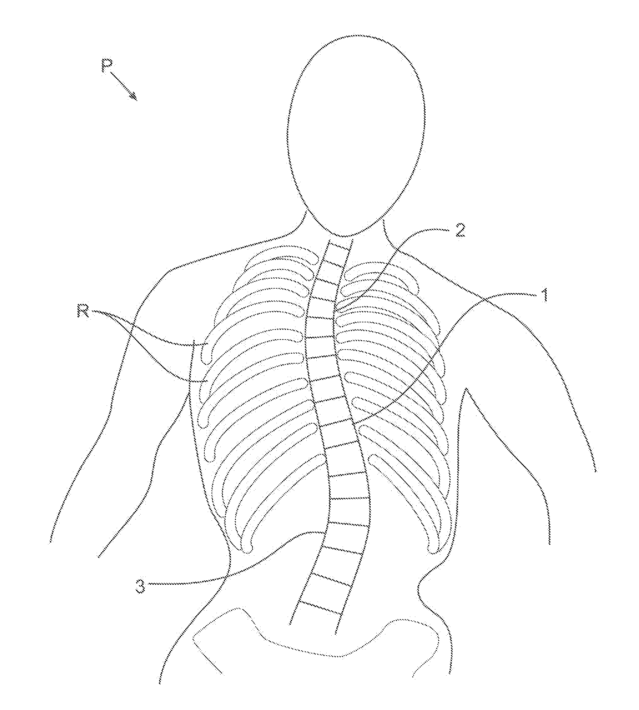
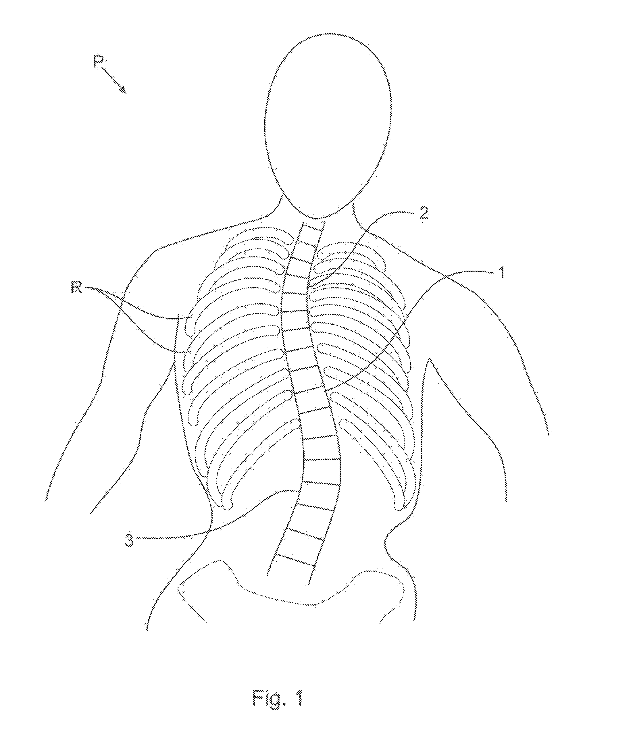
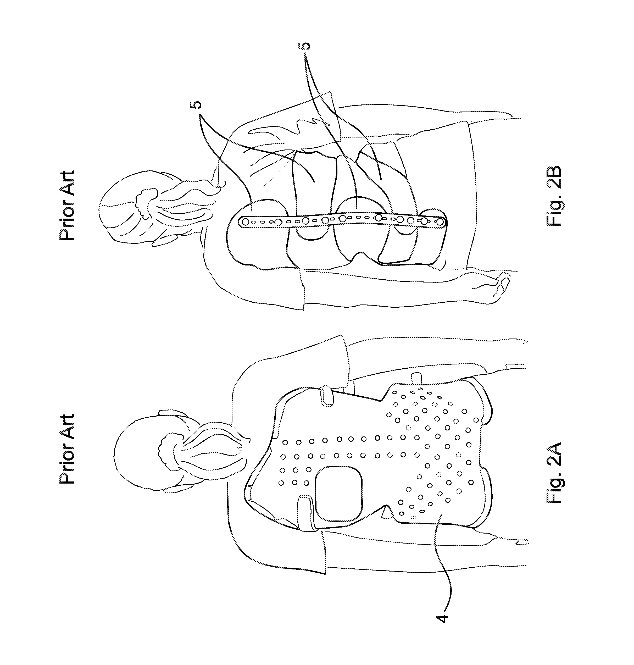
  • Percutaneous method for aligning a spine using deployable bone anchors
  • Percutaneous method for aligning a spine using deployable bone anchors
  • Percutaneous method for aligning a spine using deployable bone anchors

Examples


Embodiment Construction

[0055]At the outset, it should be appreciated that like drawing numbers on different drawing views identify identical structural elements of the invention. It also should be appreciated that figure proportions and angles are not always to scale in order to clearly portray the attributes of the present invention.

[0056]While the present invention is described with respect to what is presently considered to be the preferred embodiments, it is understood that the invention is not limited to the disclosed embodiments. The present invention is intended to cover various modifications and equivalent arrangements included within the spirit and scope of the appended claims.

[0057]Furthermore, it is understood that this invention is not limited to the particular methodology, materials and modifications described and as such may, of course, vary. It is also understood that the terminology used herein is for the purpose of describing particular aspects only, and is not intended to limit the scope...


PUM


Abstract

The present invention broadly comprises an assembly for performing a gradual lateral spinal alignment of a spine. The assembly includes an inflatable bone anchor that includes an inflatable balloon, a hollow tube attached to the balloon and attached to an external support, such as a brace. The inflatable balloon extends into or through a vertebra of the misaligned spine and deployed. The inflatable balloon is pulled using the vertebra and attached to the brace to pull the spine into alignment. The device allows the spine to be gradually placed into alignment helping to avoid trauma on the spine and surrounding tissue.

Description

CROSS REFERENCE TO RELATED APPLICATIONS[0001]This application is filed under 35 U.S.C. §120 as a continuation-in-part patent application of U.S. patent application Ser. No. 13 / 644,365, filed Oct. 4, 2012, which application is incorporated herein by reference in its entirety.FIELD OF THE INVENTION[0002]The present invention relates to the field of surgical devices, particularly to orthopedic surgical device, and more particularly to corrective devices related to the spine.BACKGROUND OF THE INVENTION[0003]Scoliosis is a disorder that causes an abnormal curve of the spine, or backbone. Patients with scoliosis develop abnormal curves to either side of the body's median line (lateral curve) and the bones of the spine twist on each other like a corkscrew. Scoliosis is about two times more common in girls than boys. It can be seen at any age, but it is most common in those over 10 years old.[0004]Often, the cause of scoliosis is unknown and is described based on the age when scoliosis deve...

Claims


Application Information

Patent Timeline
IPC IPC(8): A61B17/88A61B17/70A61B17/86
CPCA61B17/8869A61B17/70A61B17/8685A61B17/66A61B17/683A61B17/686A61B17/7053A61B17/7059A61B17/7077A61B17/7083A61B17/8855A61B2017/00004A61B2017/565A61B17/1757A61B17/844A61B17/885A61B17/8852A61B17/8858A61B17/8866A61B2017/567A61B2017/681
Inventor SUDDABY, LOUBERT S.
Owner SUDDABY LOUBERT S
Learn More