Centrifugal blower system and fuel cell incorporating same

a centrifugal blower and fuel cell technology, applied in the direction of battery/cell propulsion, liquid fuel engine, cell components, etc., can solve the problems of difficult control and fine tuning of the blower output, and achieve the effect of optimum blower performance, greater power, and more power

Active Publication Date: 2015-07-09
WATT FUEL CELL CORP
View PDF11 Cites 2 Cited by
  • Summary
  • Abstract
  • Description
  • Claims
  • Application Information

AI Technical Summary

Benefits of technology

[0012]The multiple centrifugal blower system herein offers several advantages over a single centrifugal blower, particularly when incorporated in a fuel cell for managing the flow of gaseous media therein.
[0013]Single centrifugal blowers require suitable control of the full range of motor rpm in order to meet fluctuating gas flow demands. Depending on the pressure and flow requirements for a particular blower application, optimum performance of the blower may be achieved by employing an impeller of relatively small size driven at relatively high rpm, e.g., 20,000 rpm and above, or an impeller of relatively large size driven at relatively low rpm, e.g., below 20,000 and more commonly, below 10,000. The first arrangement, i.e., the use of a relatively small impeller driven at relatively high rpm, requires a more powerful and specialized motor which of necessity will draw a correspondingly greater amount of power for its operation. The second arrangement, i.e., use of a relatively large impeller driven at relatively low rpm, makes control and fine tuning of the blower output more difficult due to the greater inertia of a large impeller.
[0014]In order to prevent overshoot of the target pressure and gas flow, a blower employing a relatively high inertia impeller must be overdamped when tuning the blower for its expected range of gas pressure and flow capability. The effect of this overdamping to compensate for the relatively high inertia of the impeller is to cause the blower to be slow in responding to changing, and often rapidly changing, gas flow requirements. This characteristically slow response of a single centrifugal blower possessing a relatively high inertia impeller requires a more complicated control system for quickly responding to fluctuations in gas flow demand.
[0015]Utilizing the multiple blower system of this invention for meeting the gas flow requirements of a fuel cell enables the system to benefit from both low inertia impellers for control as well as low drive motor rpm and power draw to provide required gas flow and pressure. Controlling one or more blower units in the system to provide a major portion of the target gas pressure and gas flow, e.g., 60-90% of the target gas pressure and gas flow, enables the remainder of the target gas pressure and gas flow to be provided by one or more other blower units in the system. The result of splitting the task of providing target gas flows and pressures between at least two integrated, i.e., interconnected, centrifugal blowers in accordance with the invention results in such flows and pressures being reached in less time and with greater accuracy than is possible with a single centrifugal blower unit. Additionally, the power draw and noise level are low in the blower system of the invention since the blower impellers do not require high rpm for their operation.
[0016]Thus, in its integrated, or interconnected, arrangement of multiple centrifugal blowers inherently possessing smaller inertial forces than a single centrifugal blower of comparable gas flow capability, the centrifugal blower system herein provides improved response times and control over a broad range of gas pressure and gas flow requirements than that of a single centrifugal blower unit.

Problems solved by technology

The second arrangement, i.e., use of a relatively large impeller driven at relatively low rpm, makes control and fine tuning of the blower output more difficult due to the greater inertia of a large impeller.

Method used


Image

  • Centrifugal blower system and fuel cell incorporating same
  • Centrifugal blower system and fuel cell incorporating same
  • Centrifugal blower system and fuel cell incorporating same

Examples


Embodiment Construction

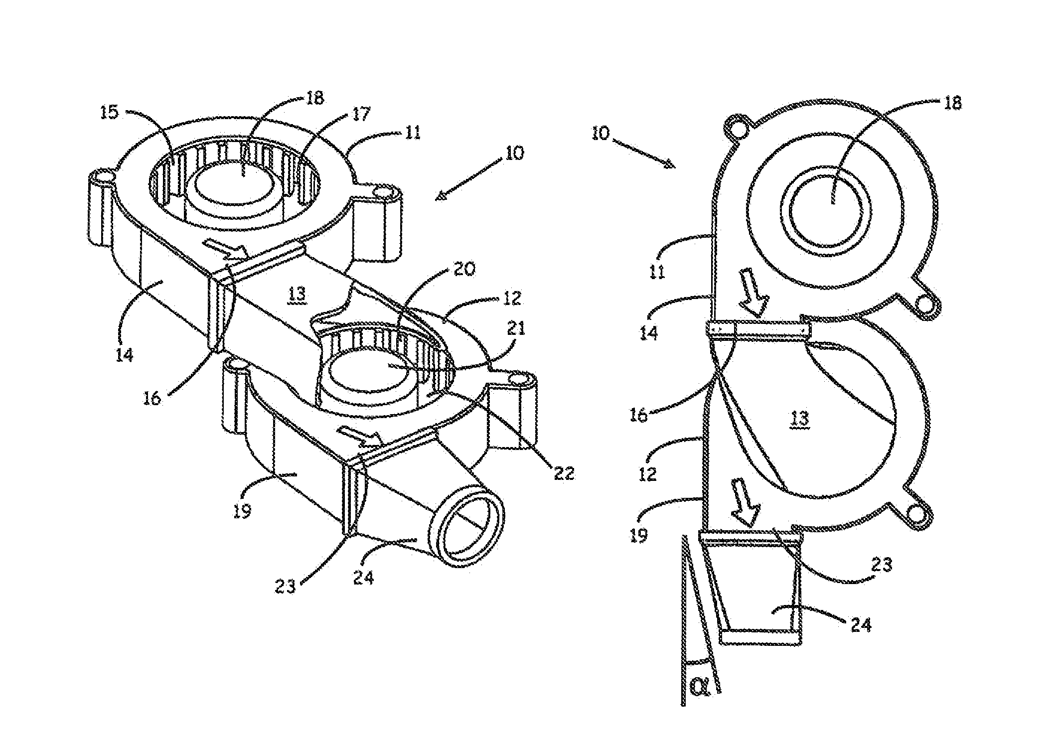
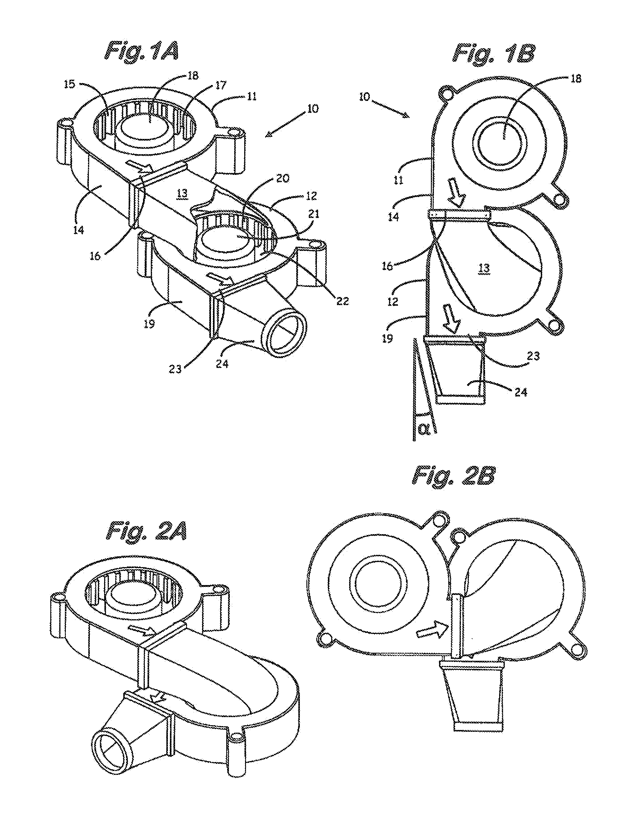
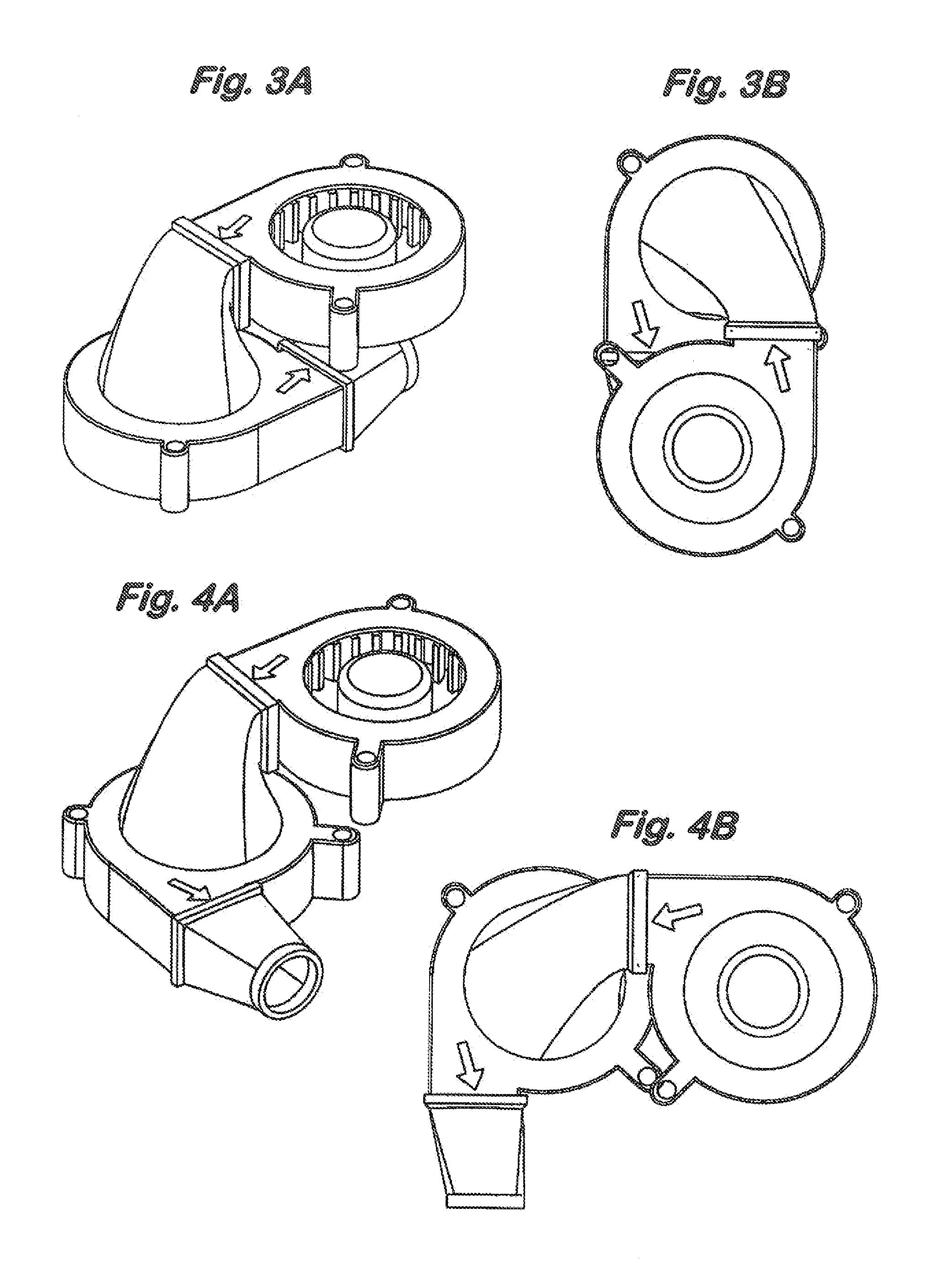
[0037]Referring to FIGS. 1A and B, in one embodiment of the centrifugal blower system of the invention, dual centrifugal blower system 10 includes a first centrifugal blower unit 11 connected to a second centrifugal blower unit 12 through duct 13. First blower unit 11 includes a casing 14 having an axial inlet 15 and a radial outlet 16, an impeller 17 disposed within casing 14 for drawing a gaseous medium at a first pressure into axial inlet 15 and expelling gaseous medium at a second higher pressure through radial outlet 16 and an electric motor 18 for driving impeller 17. Second blower unit 12 includes a casing 19 and, as shown by the cutaway section of duct 13 in FIG. 1A, an impeller 20 disposed within casing 19 and driven by electrical motor 21 and an axial inlet 22 for receiving gas medium discharged from outlet 16 of first blower unit 11. Second blower unit further includes a radial outlet 23 and outlet gas stream housing 24.

[0038]The arrows in FIGS. 1A and 1B and in the other...


PUM


Abstract

A centrifugal blower system includes a series of blower units, each blower unit in the series comprising a casing having an axial inlet and a radial outlet, an impeller disposed within the casing for drawing a gaseous medium at a first pressure into the inlet and expelling gaseous medium at a second higher pressure through the outlet and a motor for driving the impeller, and, a duct connecting the outlet of at least one blower unit in the series with the inlet of at least one other blower unit in the series.

Description

REFERENCE TO PRIOR APPLICATIONS[0001]This application is a continuation application of application Ser. No. 13 / 168,280, filed Jun. 24, 2011, the entire contents of which are incorporated herein by reference.BACKGROUND OF THE INVENTION[0002]This invention relates to centrifugal blowers and to fuel cells incorporating same.[0003]Centrifugal blowers, or centrifugal fans, are a well known type of device for providing a flow or movement of a gaseous medium. A common type of centrifugal blower includes a housing having an axially directed gas inlet and a radially directed gas outlet, an impeller disposed within the housing for drawing gas at a first pressure into the inlet and expelling gas at a second higher pressure through the outlet and a motor for driving, i.e., spinning, the impeller. Variations of this general type of centrifugal blower are disclosed in, e.g., U.S. Pat. Nos. 4,917,572; 5,839,879; 6,877,954; 7,061,758; 7,351,031; 7,887,290; 7,891,942, and, U.S. 2006 / 0051203, the ent...

Claims


Application Information

Patent Timeline
Patent Type & Authority Applications(United States)
IPC IPC(8): F04D25/16F04D17/12
CPCF04D17/12F04D25/166F04D17/16Y02T10/70Y02E60/50H01M8/04089H01M2008/1293H01M8/243B60L50/50F04D25/16H01M8/04082H01M8/04746F04D29/281H01M8/04H01M8/004H01M8/04776H01M8/12H01M2300/0071
Inventor DEWALD, PAULFINNERTY, CAINEDONLEY, ROBERT P.
Owner WATT FUEL CELL CORP
Why Eureka
Try Eureka