Wiring substrate, droplet ejection head, printing apparatus, electronic device, and manufacturing method for wiring substrate
a manufacturing method and droplet technology, applied in the direction of resistive material coating, printed circuit non-printed electric components association, final product manufacturing, etc., can solve the problems of deteriorating shape accuracy, short circuits of wires, uneven surface of recessed section,
- Summary
- Abstract
- Description
- Claims
- Application Information
AI Technical Summary
Benefits of technology
Problems solved by technology
Method used
Image
Examples
first embodiment
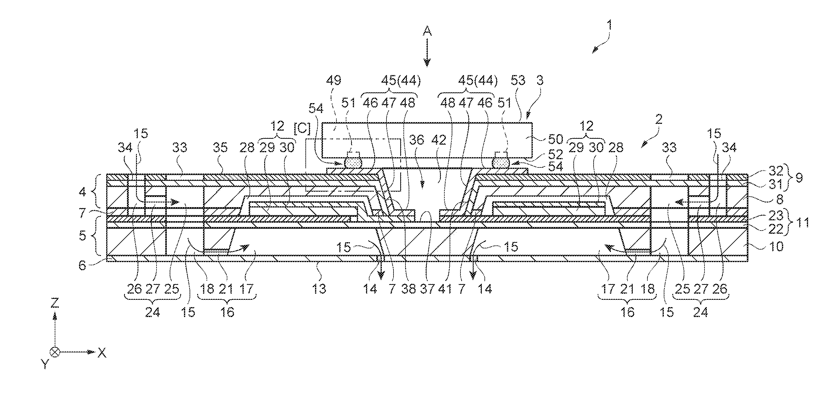
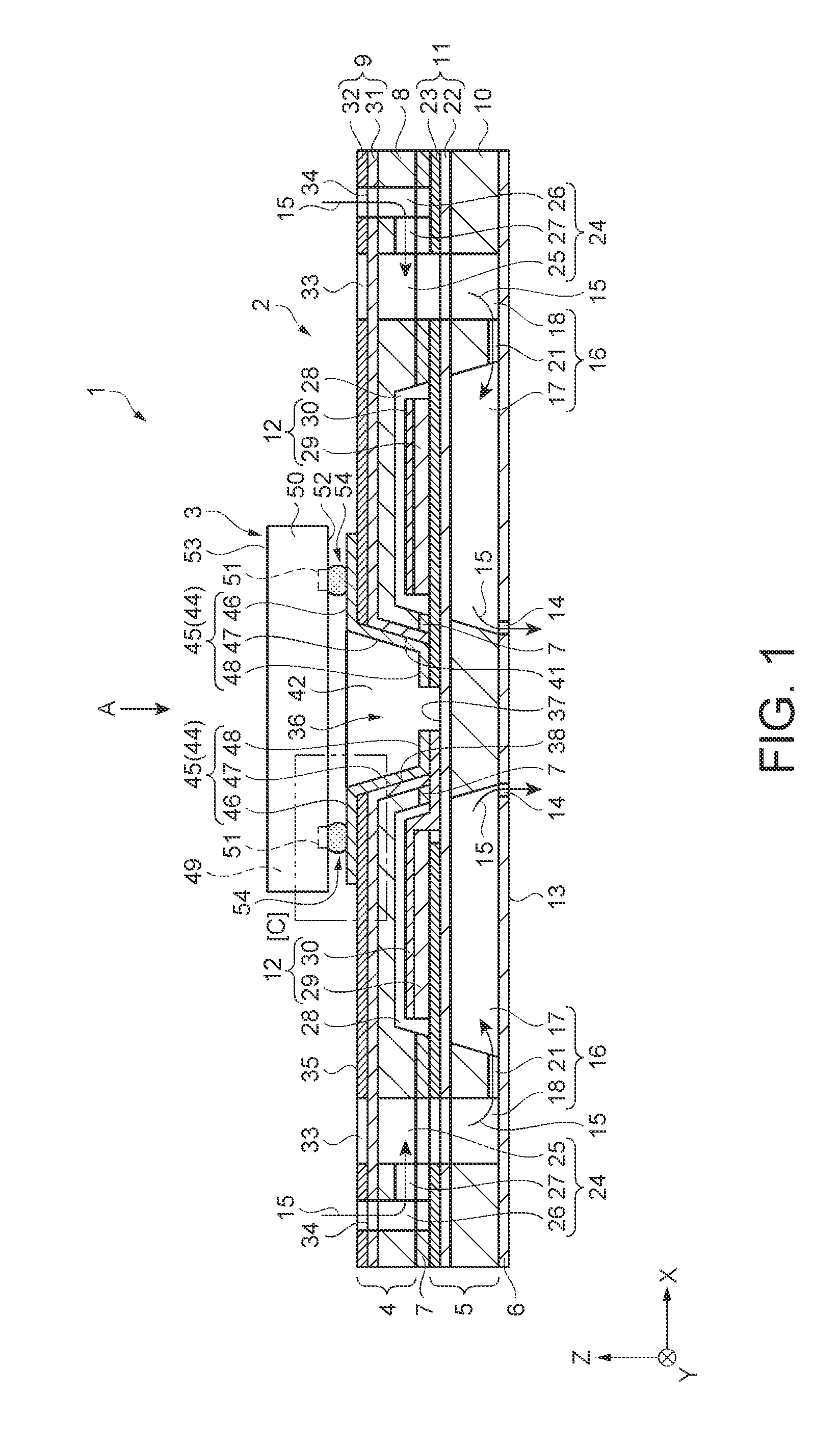
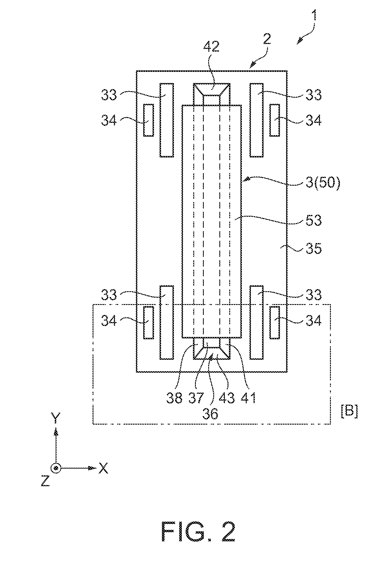
[0050]A droplet ejection head according to a first embodiment is explained with reference to FIGS. 1 to 6B. FIG. 1 is a schematic side sectional view showing the structure of the droplet ejection head. FIG. 2 is a schematic plan view showing the structure of the droplet ejection head and is a view of the droplet ejection head viewed from an arrow A direction in FIG. 1. FIG. 3 is a main part schematic plan view showing the structure of the droplet ejection head and is an enlarged detailed view of an area [B] surrounded by an alternate long and short dash line in FIG. 2.
[0051]As shown in FIGS. 1 and 2, a droplet ejection head 1 includes a base substrate 2 functioning as a tabular wiring substrate and an IC (Integrated Circuit) package 3 arranged on the base substrate 2. The droplet ejection head 1 is mounted on a printing apparatus (a droplet ejection apparatus). The droplet ejection head 1 can eject ink on a recording medium as droplets and perform printing on the recording medium.
[0...
second embodiment
[0104]A droplet ejection head according to a second embodiment is explained with reference to schematic diagrams of FIGS. 7A to 7C for explaining the structure of wires in a recessed section. FIG. 7A is a main part schematic side sectional view in the recessed section 36. FIG. 7B is a main part schematic side sectional view in an adhesive film. FIG. 7C is a main part schematic perspective view in the recessed section and is a diagram in which the sealing film 55 shown in FIGS. 4A and 4B are omitted. This embodiment is different from the first embodiment in that the films 56 shown in FIGS. 4A and 4B are omitted and the shape of the recessed section 57 is different. Note that explanation is omitted concerning similarities to the first embodiment.
[0105]In this embodiment, as shown in FIGS. 7A to 7C, a droplet ejection head 61 includes a base substrate 62. In the base substrate 62, the vibrating plate 11 and the reservoir forming substrate 8 are bonded by an adhesive film 63. In the adh...
third embodiment
[0111]A droplet ejection head according to a third embodiment is explained with reference to schematic diagrams of FIGS. 8A to 8C for explaining the structure of wires in a recessed section. FIG. 8A is a main part schematic side sectional view in the recessed section 36. FIG. 8B is a main part schematic side sectional view in the adhesive film. FIG. 8C is a main part schematic perspective view in the recessed section 36 and is a diagram in which the sealing film 55 is omitted. This embodiment is different from the first embodiment in that the shape of the recessed section 57 shown in FIGS. 4A to 4C is different. Note that explanation is omitted concerning similarities to the first embodiment.
[0112]In this embodiment, as shown in FIGS. 8A to 8C, a droplet ejection head 68 includes a base substrate 69. In the base substrate 69, the vibrating plate 11 and the reservoir forming substrate 8 are bonded by an adhesive film 70. A surface of the adhesive film 70 in contact with the wires 45 ...
PUM
| Property | Measurement | Unit |
|---|---|---|
| Depth | aaaaa | aaaaa |
| Depth | aaaaa | aaaaa |
| Electrical conductor | aaaaa | aaaaa |
Abstract
Description
Claims
Application Information
 - R&D
- Intellectual Property
- Life Sciences
- Materials
- Tech Scout
- Unparalleled Data Quality
- Higher Quality Content
- 60% Fewer Hallucinations
Browse by: Latest US Patents, China's latest patents, Technical Efficacy Thesaurus, Application Domain, Technology Topic, Popular Technical Reports.
© 2025 PatSnap. All rights reserved.Legal|Privacy policy|Modern Slavery Act Transparency Statement|Sitemap|About US| Contact US: help@patsnap.com


