Full denture base manufacturing method

a manufacturing method and full denture technology, applied in the field of full denture base manufacturing method, can solve the problems of inability to obtain data regarding bite position and height, and achieve the effect of easy copying and transfer, rapid manufacturing and eas

Active Publication Date: 2015-07-09
GC CORP
View PDF6 Cites 9 Cited by
  • Summary
  • Abstract
  • Description
  • Claims
  • Application Information

AI Technical Summary

Benefits of technology

The present invention provides a method for manufacturing a full denture base using a set of impression trays with U-shaped grooves. The impression material is applied to the grooves and is set in place by pressing against the alveolar ridge. The method allows for easy determination of bite position and height simultaneously. An additional impression material can be applied between the flat top surfaces of the projecting parts to transfer data related to bite position and height. The impression trays and materials are then removed and replaced with a model material to manufacture an edentulous jaw model. The full denture base can be manufactured quickly and easily with this method.

Problems solved by technology

However, this impression tray is merely for taking the impression of the alveolar ridge (refer to paragraph 0001 of specification of Patent Document 1), and no data can be obtained with respect to the bite position and height.

Method used


Image

  • Full denture base manufacturing method
  • Full denture base manufacturing method
  • Full denture base manufacturing method

Examples


Embodiment Construction

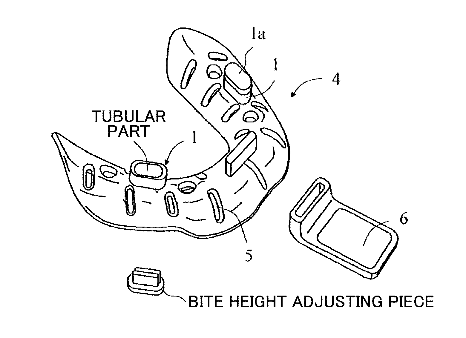
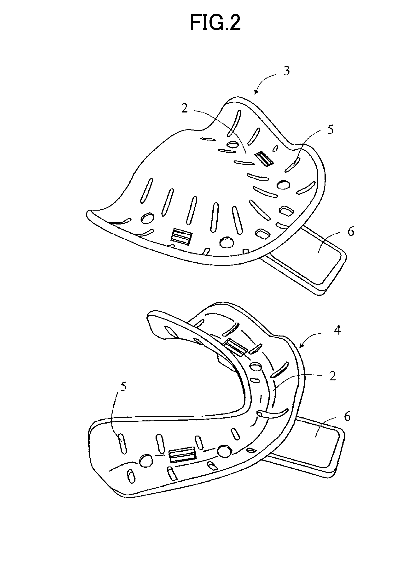
[0024]A detailed description will hereinafter be given of the full denture base manufacturing method according to the present invention, by referring to the drawings. In the drawings, An U-shaped groove 2 has a front surface side on which an impression material is to be applied and provided with projecting parts 1 on a back surface side thereof. In addition, the projecting part 1 has a flat top surface 1a, as illustrated in FIGS. 1 and 3-5.

[0025]When the projecting parts 1 are provided on the back surface of each of a maxillary impression tray 3 and a mandibular impression tray 4 which will be described later, at the U-shaped groove 2 for positioning each of left and right alveolar ridges from a first molar part to a premolar part, a pair of projecting parts 1 is arranged on the left and right at approximately an intermediate part between the front teeth and the molars. Hence, by adjusting positions in a state in which at least a part of the flat top surfaces 1a of the projecting pa...


PUM


Abstract

A full denture base manufacturing method is provided that can easily manufacture a full denture base, using a set of maxillary impression tray and a mandibular impression tray for taking an impression from a patient including an edentulous patient.An impression material is applied on each of a maxillary impression tray 3 and a mandibular impression tray 4 configuring a set of impression trays, and respectively having a U-shaped groove, the U-shaped groove having a front surface side on which the impression material is to be applied and being provided with projecting parts 1 on a back surface side thereof, and the applied impression material is pressed against an alveolar ridge within an oral cavity and set, to determine bite position and height in a state in which at least a part of flat top surfaces of the projecting parts 1 contact each other, the second impression material is applied between back surfaces of the impression trays 3, 4 and set in a state in which at least a part of the flat top surfaces contact each other, each of the impression trays 3, 4 and the impression material are removed from within the oral cavity in one piece of the maxillary and mandibular impression trays, or separately in two pieces of the maxillary and mandibular impression trays, and a model material is thereafter injected to each impression material on the removed maxillary and mandibular impression trays and set, in order to manufacture an edentulous jaw model, and the edentulous jaw model is set on an articulator in a state in which the bite position and height that are determined in advance are reflected, in order to manufacture a full denture base.

Description

TECHNICAL FIELD[0001]The present invention relates to a full denture base manufacturing method that can easily manufacture a full denture base, using a set of a maxillary impression tray and a mandibular impression tray.BACKGROUND ART[0002]Generally, in odontotherapy, when taking an intraoral impression in a preparation stage of manufacturing prostheses, an impression material such as silicone impression materials, alginate impression materials, and the like is used. An impression tray is used to intraorally hold such an impression material. The impression material is applied on the impression tray that is inserted into an oral cavity of a patient, and after the impression material is pressed for taking an impression and is set, the impression tray is removed from the oral cavity of the patient in a state in which the set impression material is integrally held on the impression tray.[0003]When taking such an impression from an edentulous patient (including a substantially edentulous...

Claims


Application Information

Patent Timeline
IPC IPC(8): A61C13/01A61C9/00A61C13/34
CPCA61C13/01A61C9/0006A61C13/34A61C13/04F04C2270/041
Inventor SUGA, TAKEOITODA, MASATAKAYASAKI, HIDEAKIYOKOYAMA, YASUHIRONOMURA, SHUICHIKAMOHARA, HIROSHI
Owner GC CORP
Why Eureka
Try Eureka